Process for improving inline tailings treatment

a technology for tailings and treatment, applied in separation processes, transportation and packaging, chemistry apparatuses, etc., can solve the problems of becoming contaminated with tailings and other waste materials, and achieve the effect of improving treatment efficiency and improving performan

Inactive Publication Date: 2012-06-07
S P C M SA
View PDF9 Cites 28 Cited by
  • Summary
  • Abstract
  • Description
  • Claims
  • Application Information

AI Technical Summary

Benefits of technology

[0019]One or more static mixer could be added in the process to improve the efficiency of the treatment. Static mixer could be added in main stream between the reinjection point and the polymer injection point, and/or after the polymer injection point, and/or in the split st

Problems solved by technology

Treatment of tailings and other waste material have become a technical, environmental and public policy issue.
It has been and still is a sizable i

Method used


Image

  • Process for improving inline tailings treatment
  • Process for improving inline tailings treatment
  • Process for improving inline tailings treatment

Examples


example 1

Split Stream Process Model 1

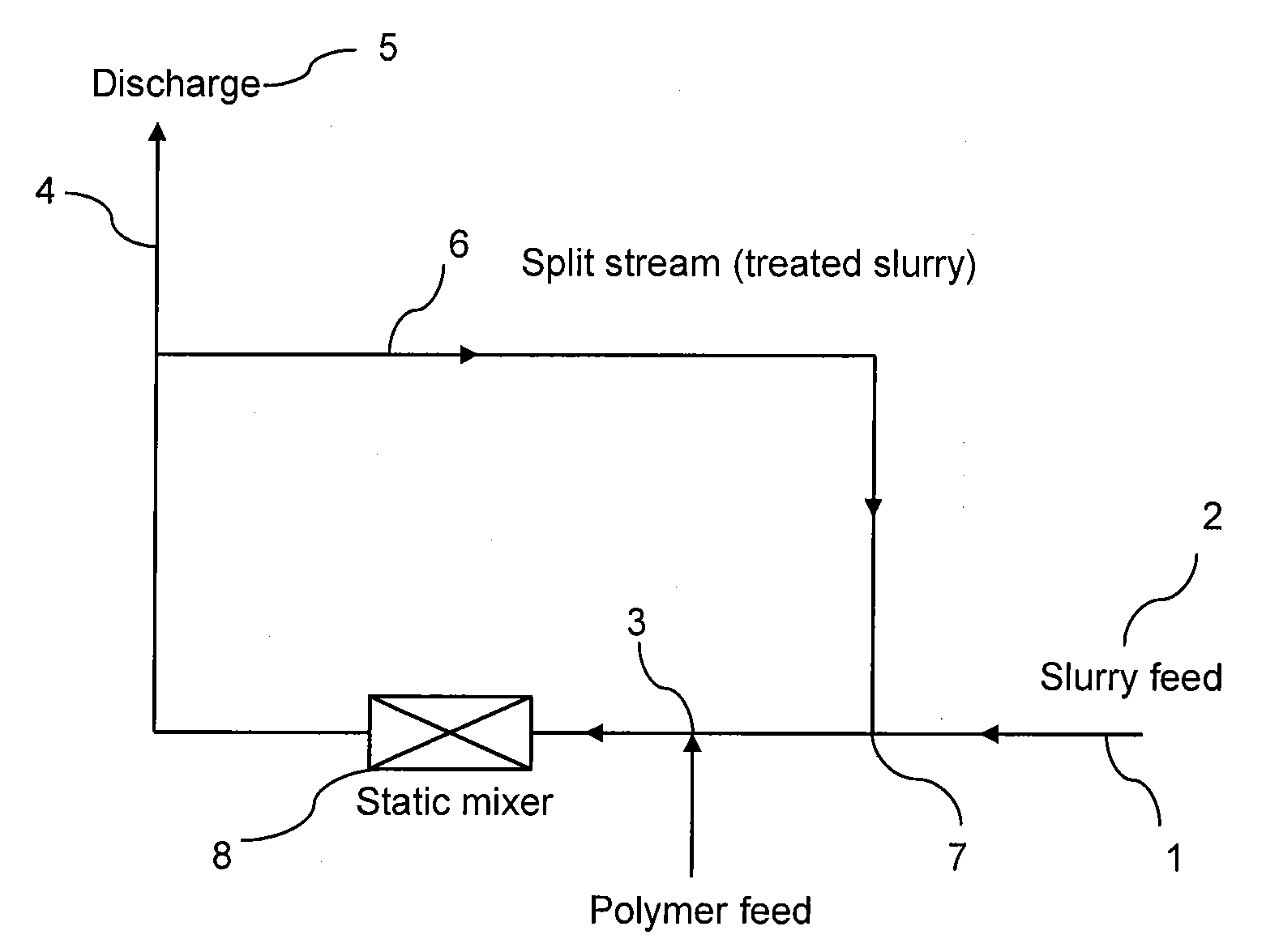
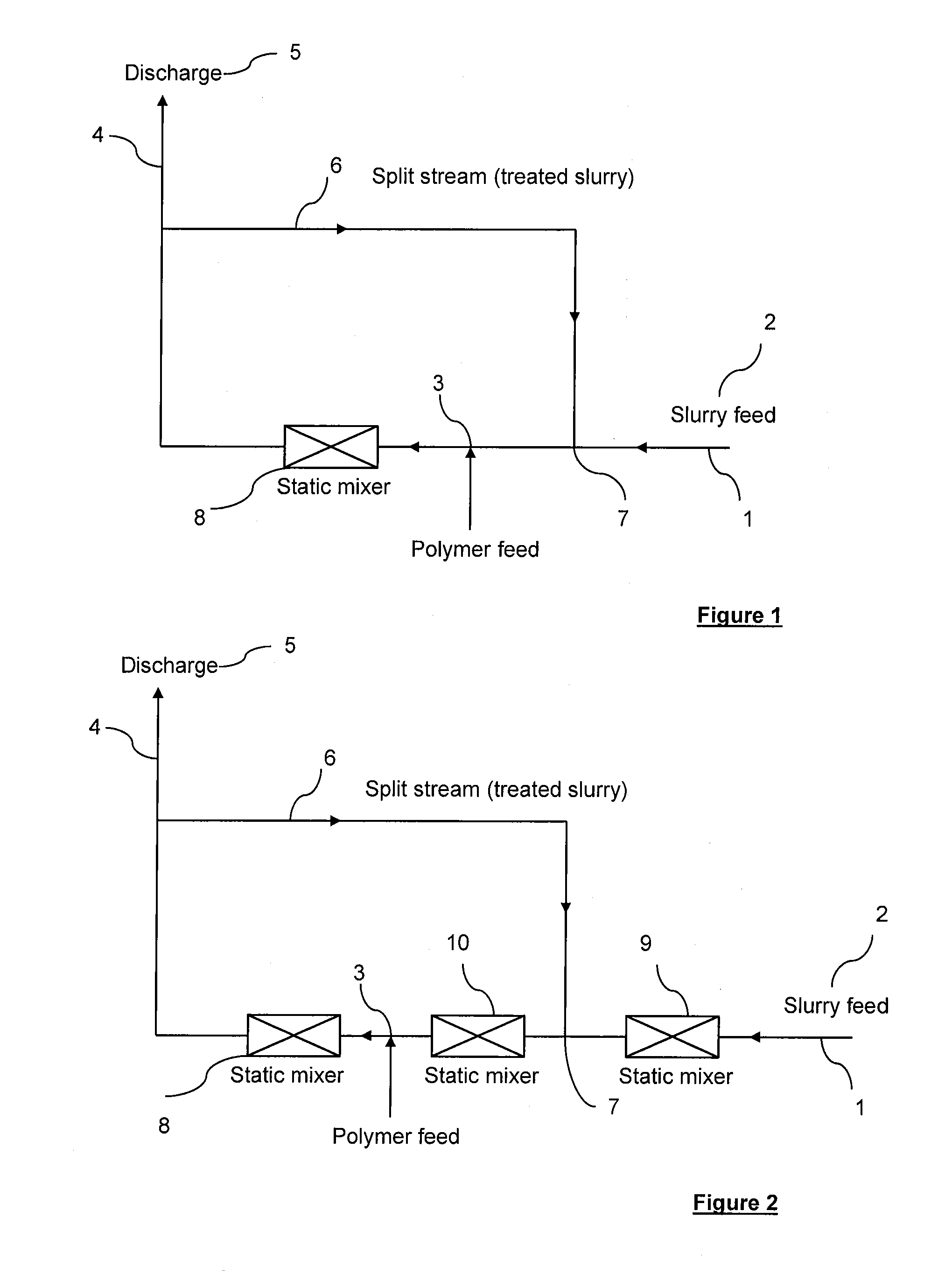
[0052]FIG. 1 is a scheme illustrating a first embodiment of the installation of the invention. Accordingly, the installation comprises a main stream (1) within which circulates an in-line flow of slurries (2). The main stream contains a polymer injection point (3) through which at least one polymer is injected. The main stream is then divided into two streams respectively:[0053]a discharge stream (4) which directly transfers a part of treated slurries to the deposit area (5),[0054]a split stream (6) which reintroduces the other part of treated slurries into the main stream (1) through the reinjection point (7) prior to the polymer injection point (3). As shown on the scheme, the installation is also equipped with a static mixer (8).

example 2

Split Stream Process Model 2

[0055]FIG. 2 is a scheme illustrating a second embodiment of the installation of the invention. This installation differs from the first one in that it contains two additional static mixers. The second static mixer (9) is located before the reinjection point (7) and the third one is located between the reinjection point (7) and the injection point (3).

examples 3

Effect of Split Stream on Mature Fine Tailings Dewatering

Test Procedure

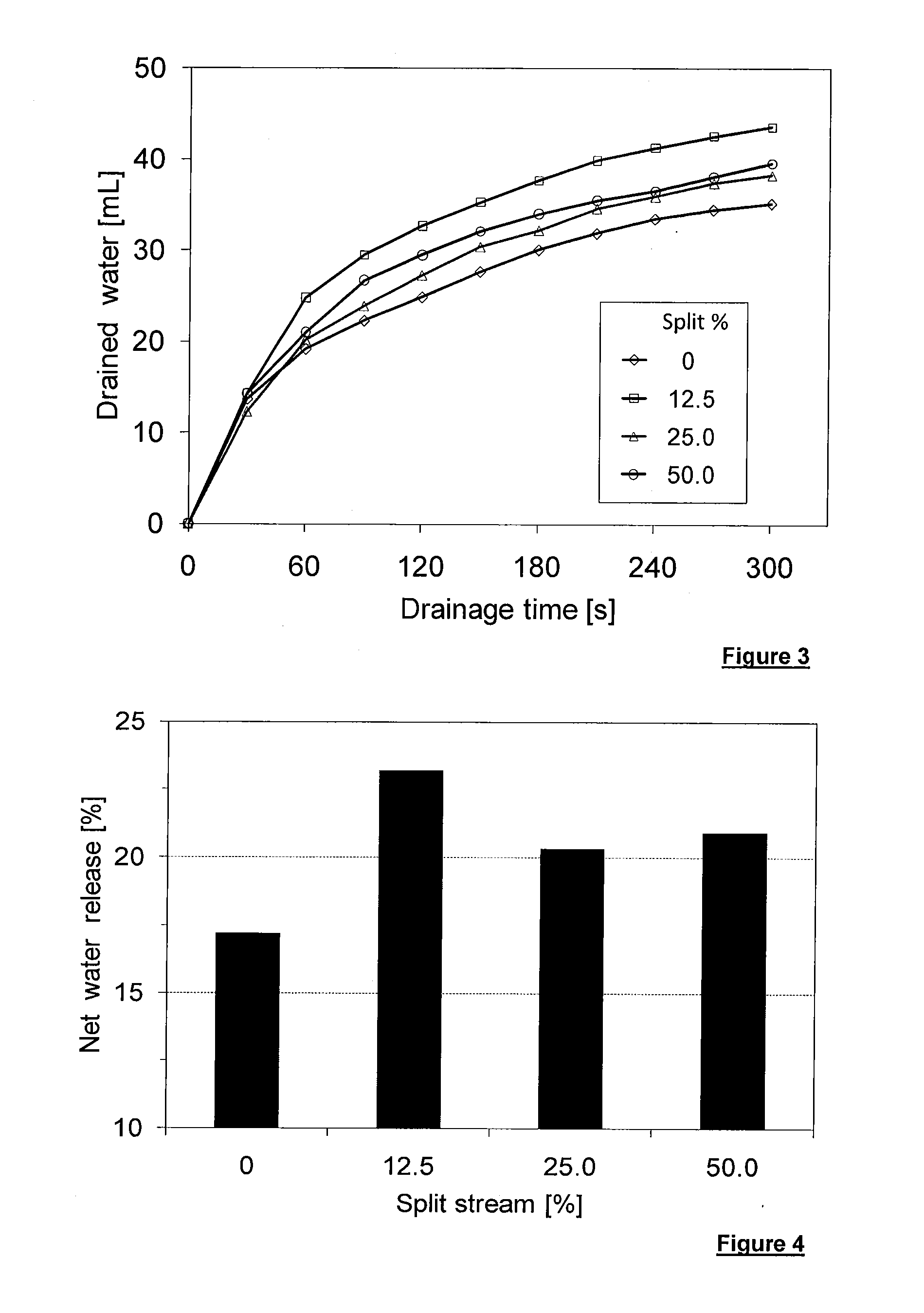
[0056]200 g of oil sands mature fine tailings of 48.9% solids was mixed with the desired volume of 0.2 wt % solution of A-3338. After mixing, a known percentage of slurry was collected (subsampled) and additional untreated MFT and polymer solution were added into it. More mixing was applied to achieve the optimal flocculation. The additional untreated MFT and polymer were added in amounts so that a total MFT used was 200 g and final polymer dosage was unchanged for all tests. Because the final amount of treated MFT was the same with the initial MFT (200 g), the percentage of collected slurry was defined as a percentage of split stream.

[0057]After flocculation, a gravity drainage test was performed and net water release was also determined at 90 minutes.

Results

[0058]As shown in FIG. 3, split stream increased significantly drainage rate. The highest drainage rate was obtained for 12.5% of split stream.

[0059]As show...


PUM

PropertyMeasurementUnit
Fractionaaaaaaaaaa
Fractionaaaaaaaaaa
Fractionaaaaaaaaaa

Abstract

A process for improving inline mineral slurries treatment comprises successively: providing an in-line flow of slurries in a main stream; introducing at least one polymer into the main stream through at least one polymer injection point to cause dispersion of the polymer and to start the coagulation and/or the flocculation of slurries to produce treated slurries; and splitting the main stream containing treated slurries into two streams respectively: a discharge stream which directly transfers a part of treated slurries to the deposit area, and a split stream which reintroduces the other part of treated slurries into the main stream through at least a reinjection point in a location prior to the at least one polymer injection point.

Description

TECHNICAL FIELD[0001]The present invention relates to the treatment of material comprising an aqueous liquid with dispersed particulate solids.[0002]The invention relates to a process for improving the inline treatment process of slurries or tailings resulting from mineral processing.BACKGROUND OF THE ART[0003]Treatment of tailings and other waste material have become a technical, environmental and public policy issue.[0004]Mineral processes produce a huge quantity of waste material slurries or tailings which can be in aqueous suspension with dispersed particulate solids, for instance sand, clay, shale and other minerals. It has been and still is a sizable issue for the mining industry to treat these tailings and accomplish liquid solid separation at the processes end to separate liquid from the solid.[0005]It is common practice to use synthetic or natural polymers such as coagulants and flocculants to separate the solids from the liquid.[0006]Inline flocculation is a well-known pro...

Claims


Application Information

Patent Timeline
IPC IPC(8): B01D21/01
CPCB01F5/102B09B1/00B01F2003/1285
Inventor DANG-VU, TRONGCAGLE, PHIL
Owner S P C M SA
Why Eureka
Try Eureka