Arrangement and method for testing an electric power generation system

a technology of electric power generation and arrangement, applied in the direction of power supply testing, instruments, machines/engines, etc., to achieve the effect of improving flexibility and extending the testing ability of the arrangemen

Inactive Publication Date: 2012-06-07
SIEMENS AG
View PDF5 Cites 20 Cited by
  • Summary
  • Abstract
  • Description
  • Claims
  • Application Information

AI Technical Summary

Benefits of technology

[0009]According to an embodiment the component is connected to a reference point (such as a ground point or a particular phase). If the electrical adjustment system comprises one or more components a number of components may be connected to a same reference point. Thereby, discharging of a power signal to the reference point is enabled for extending the testing ability of the arrangement for testing the electrical power generation system.
[0010]According to an embodiment the adjustment system comprises a reference point switch via which the component is connected to the reference point. Thus, a current flow through the component towards the reference point may selectively be allowed or not allowed by switching the reference point switch. Thereby, an improved flexibility is provided for testing the electric power generation system.

Problems solved by technology

Thereby, problems or failures of the electric power generation system upon particular electric conditions or utility grid parameters may be identified and discovered already at the manufacturing site or the test site at which only the auxiliary grid is available.

Method used


Image

  • Arrangement and method for testing an electric power generation system
  • Arrangement and method for testing an electric power generation system
  • Arrangement and method for testing an electric power generation system

Examples


Embodiment Construction

[0028]The illustration in the drawing is schematic. It is noted that in different figures, similar or identical elements are provided with the same reference signs or with reference signs, which are different from the corresponding reference signs only within the first digit.

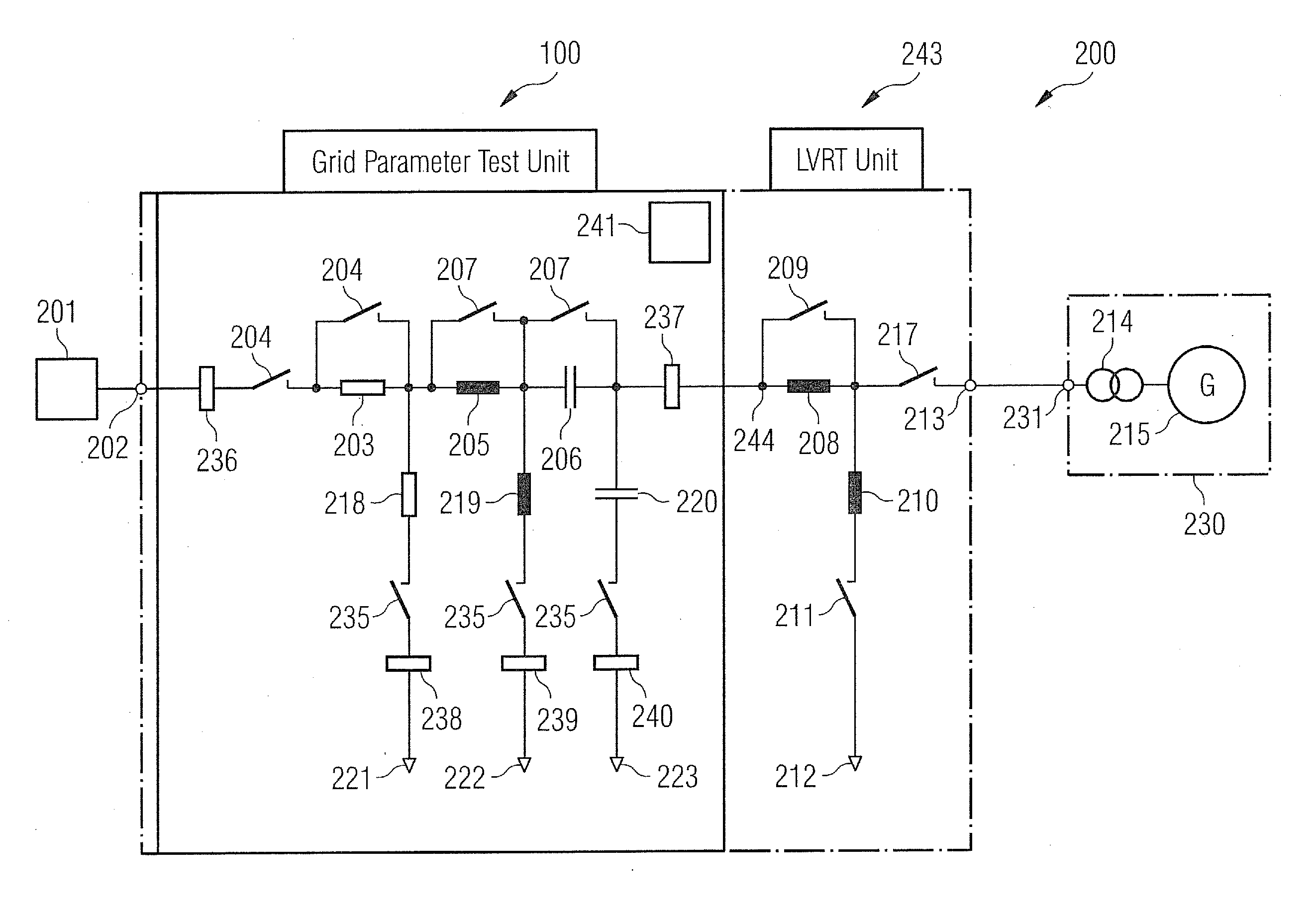
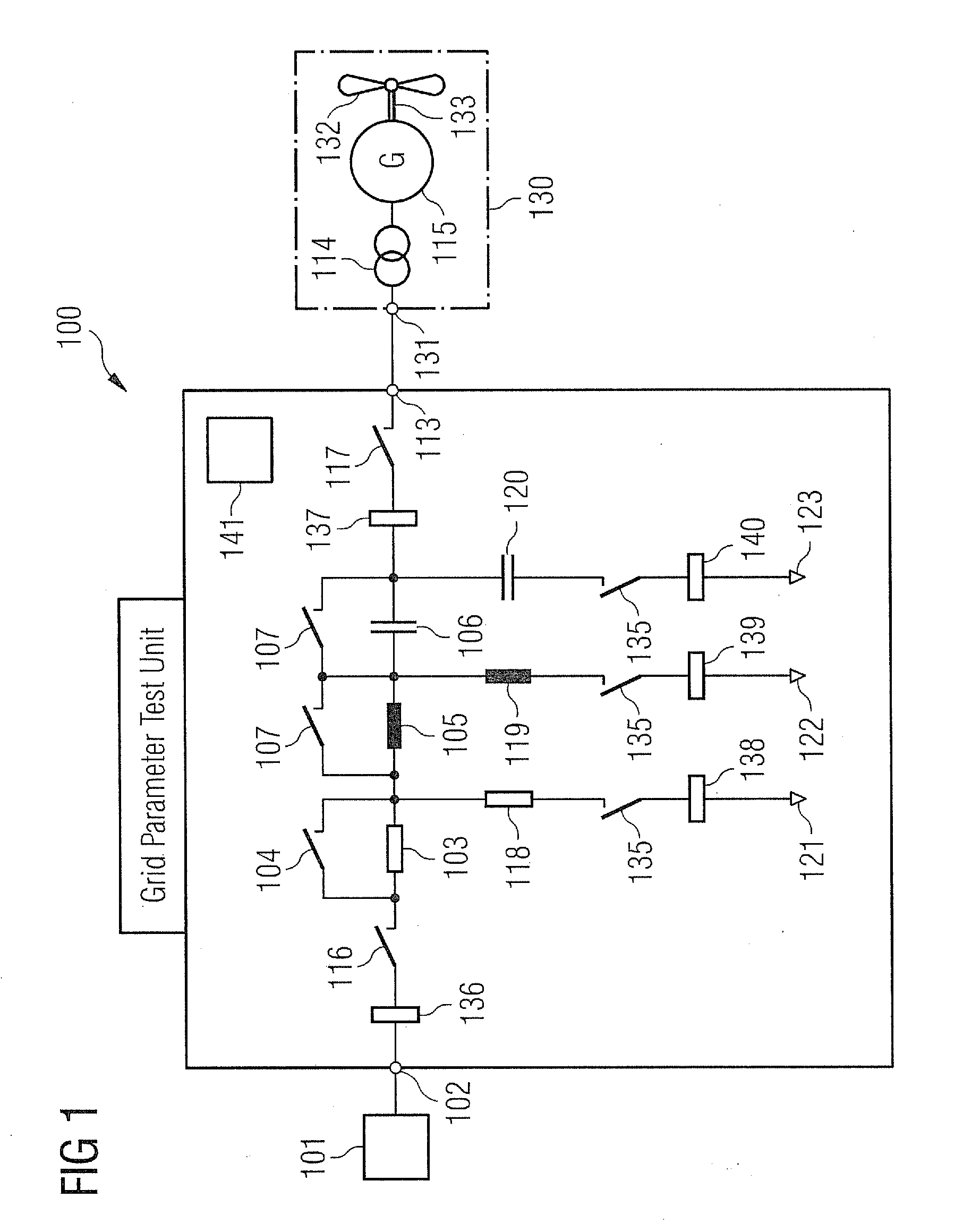
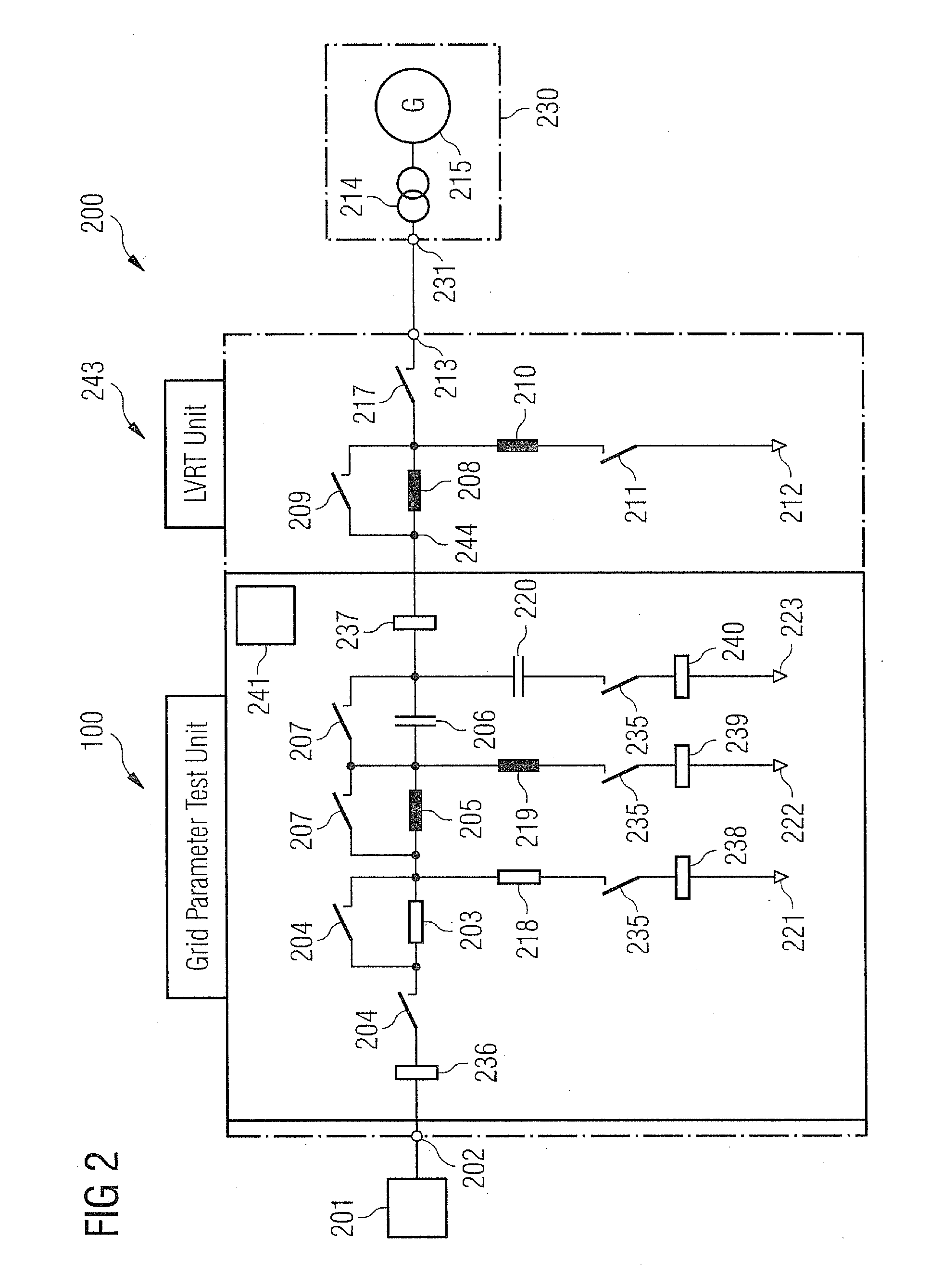
[0029]FIG. 1 schematically illustrates a circuit diagram of an ar-″ rangement 100 for testing an electric power generation system 130. The arrangement 100 (also referred to as test arrangement) comprises an input terminal 113 for connecting the arrangement 100 to an output terminal 131 of the electric power generation system 130.

[0030]In the illustrated embodiment the electric power generation system 130 is a wind turbine system comprising a rotor 133 having mounted thereon rotor blades 132, wherein the rotor drives a generator 115 via the rotor shaft 133. The generator 115 generates electric energy which is supplied to a trans-former 114 to transform the voltage of the energy power signal to an appropriate valu...


PUM


Abstract

An arrangement is provided for testing an electric power generation system, for example, a wind turbine system, which is to be connected to a utility grid having a predetermined first impedance. The arrangement includes an input terminal for connecting the arrangement to an output terminal of the power generation system. The arrangement further includes a grid terminal for connecting the arrangement to the utility grid. The arrangement further includes an electrical adjustment system connected between the input terminal and the grid terminal. The electrical adjustment system is adapted to adjust an impedance at the input terminal to the predetermined first impedance, when an auxiliary grid having a second impedance different from the first impedance is connected at the grid terminal. A corresponding method is also provided.

Description

FIELD OF INVENTION[0001]The present invention relates to an arrangement and to a method for testing an electric power generation system, in particular a wind turbine system, to be connected to an utility grid having a predetermined first electrical impedance. In particular, the present invention relates to an arrangement and to a method for testing the electric power generation system, wherein the arrangement and the method are adapted to test the electric power generation system at a test site remote from a production site at which the electric power generation system eventually is supposed to be installed.ART BACKGROUND[0002]Conventionally, an electric power generation system, such as a wind turbine system, is manufactured at a manufacturing site and is eventually installed at a production site remote from the manufacturing site for producing electric energy. At the production site the electric power generation system is supposed to be connected to an electrical utility grid. The ...

Claims


Application Information

Patent Timeline
Patent Type & Authority Applications(United States)
IPC IPC(8): G01R31/40
CPCF05B2260/83Y02E10/725G01R31/343G01R27/16Y02E10/72
Inventor DREYER, THOMASWULFF, STEFFEN
Owner SIEMENS AG
Why Eureka
Try Eureka