Optical connector

Inactive Publication Date: 2012-06-07
TYCO ELECTRONICS NETHERLAND BV +1
View PDF13 Cites 22 Cited by
  • Summary
  • Abstract
  • Description
  • Claims
  • Application Information

AI Technical Summary

Benefits of technology

[0010]The film may be attached the end face of the ferrule and the end faces of the optical transports in the ferrule by a layer of adhesive. In one embodiment, the film is provided as a strip already bearing the adhesive on one side that can simply be pressed against the ferrule end face to adhere it over all of the polymer optical transports in the ferr

Problems solved by technology

Scratches and poorly polished surfaces can significantly increase insertion loss and reduce optical coupling because any air (or even vacuum) in the optical path is likely to substantially increase optical losses across the interface due to the significant difference in the index of refraction of air (or vacuum) and the index of refraction of the optical transports.
Gaps substantially increase reflections, i.e., return loss, across the interface.
Polishing is relatively expensive and/or time consuming and requires specialized and expensive equipment.
Further, it is difficult to laser cleave a polymer waveguide sufficiently fla

Method used


Image

  • Optical connector
  • Optical connector
  • Optical connector

Examples


Embodiment Construction

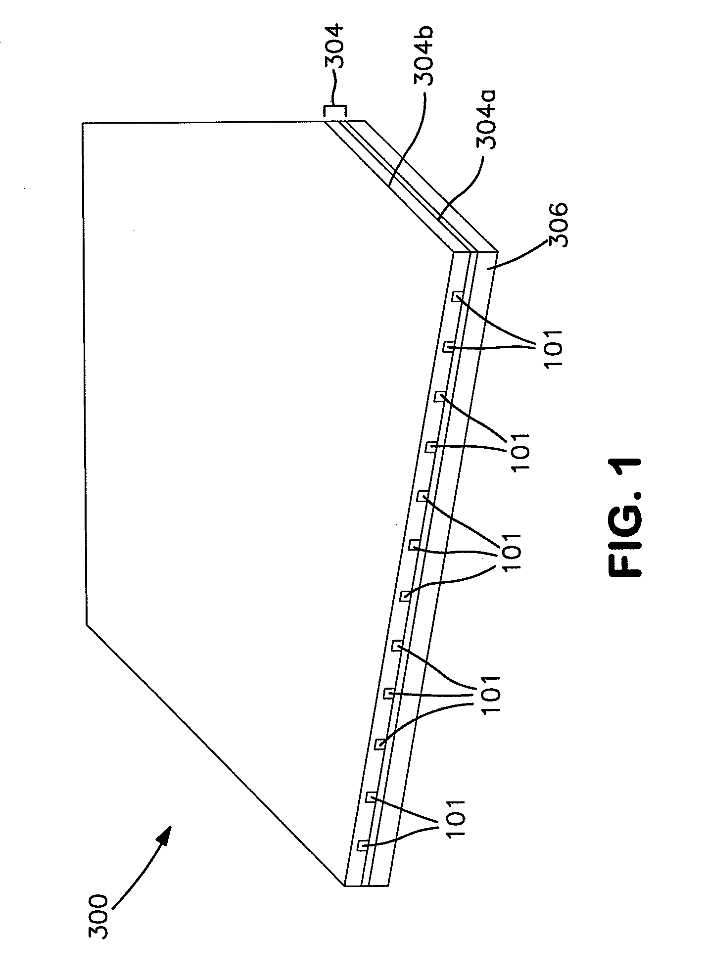
[0015]FIG. 1 is a breakaway view of an exemplary layer 300 of polymer optical waveguides such as might form the optical transports in an optical cable terminated by an optical connector. It comprises twelve parallel optical waveguides 101 embedded in planar cladding 304 supported on a polymer mechanical support layer 306. Waveguides typically are manufactured in a planar manner using epitaxial layer processes commonly associated with printed circuit board and semiconductor fabrication. For instance, a first layer 304a of cladding is deposited on top of a mechanical support substrate 306. Then, using conventional photolithography techniques, a plurality of strips of waveguide core material is deposited on top of the first cladding layer 304a to form the waveguides 101. For example, a layer of photoresist is deposited over the first cladding layer 304a and the photoresist is developed through a photolithography mask corresponding to the desired pattern of the waveguides 101 (typically...


PUM


Abstract

In accordance with the invention, the end faces of polymer optical waveguides are coated with a film that is harder than the waveguides themselves, but still sufficiently compliant to fill in scratches, gouges and other non-planarities in the end faces of the waveguides. Even further, using a single continuous sheet of the film to protect the end faces of a plurality of polymer waveguides in a connector also helps make the effective mating surfaces of all of the waveguides coplanar (i.e., longitudinally coextensive). Furthermore, if the film becomes scratched, it can be stripped off and replaced without the need to replace the waveguides or the entire connector.

Description

FIELD OF THE INVENTION[0001]The invention pertains to fiber optics. More particularly, the invention pertains to optical transports such as polymer optical waveguides that have relatively soft end faces.BACKGROUND OF THE INVENTION[0002]Optical transports such as optical fibers and optical waveguides are commonly used to transport data over both short and long distances. Such optical transports often are terminated with an optical connector that allows an end face of the optical transport to mate with the optical interface of another optical component, be it the end face of another optical transport in another optical connector, or a piece of optical or optoelectronic equipment such as an optical receiver having a photodetector for detecting light received through the optical transport or an optical transmitter having a laser transmitter or LED for inputting light into the optical transport. The term “optical component” refers to any optical or optoelectronic component to which a wav...

Claims


Application Information

Patent Timeline
IPC IPC(8): G02B6/38G02B6/26
CPCG02B6/382G02B6/4212G02B6/3847
Inventor DUIS, JEROEN ANTONIUS MARIARIETVELD, JAN WILLEMBOWEN, TERRY PATRICK
Owner TYCO ELECTRONICS NETHERLAND BV
Why Eureka
Try Eureka