Method for coating micromechanical components of a micromechanical system, in particular a watch and related micromechanical coated component

Inactive Publication Date: 2012-06-07
THE SWATCH GRP RES & DEVELONMENT LTD
View PDF18 Cites 2 Cited by
  • Summary
  • Abstract
  • Description
  • Claims
  • Application Information

AI Technical Summary

Benefits of technology

[0042]Such component can be used to eliminate the particle (debris/dust) attraction in any other macroscopic or microscopic mechanisms where at least one component can be coated with conductive diamond to prevent dust attraction.
[0043]Such mechanical components, produced for micromechanical s

Problems solved by technology

The approaches presented generally fulfil some of the tasks without being able to deliver a complete solution mainly due to the restrictions on the materials used.
Micromechanical components produced by mechanical machining (die cutting or shape cutting) exhibit two major disadvantages: firstly, they are either high priced or economically profitable only in mass production because investments are required for expensive production tools.
Secondly, these processes did reach their technical limits with the accuracy lying by +/−5 micrometers.
For instance, in the watch industry, this causes problems in the handling of the parts and in the regularity of the performance and reliability of watches on short and long terms.
A further problem of the lubricated systems is the necessity for frequent service intervals, where the movements have to be cleaned and re-lubricated.
DLC has a high sp2 content (ranging from 30 to 80%) and is amorphous carbon which hardness could not be sufficient for effective wear protection applications.
The top layer is relatively soft and wears off quickly in applications involving high friction forces.
However, nowadays the use of a radioactive element in a timepiece could be not be envisaged.
However, this anti-static surface cannot be used in mechanical systems because the siliconised surfac

Method used


Image

  • Method for coating micromechanical components of a micromechanical system, in particular a watch and related micromechanical coated component
  • Method for coating micromechanical components of a micromechanical system, in particular a watch and related micromechanical coated component

Examples


Embodiment Construction

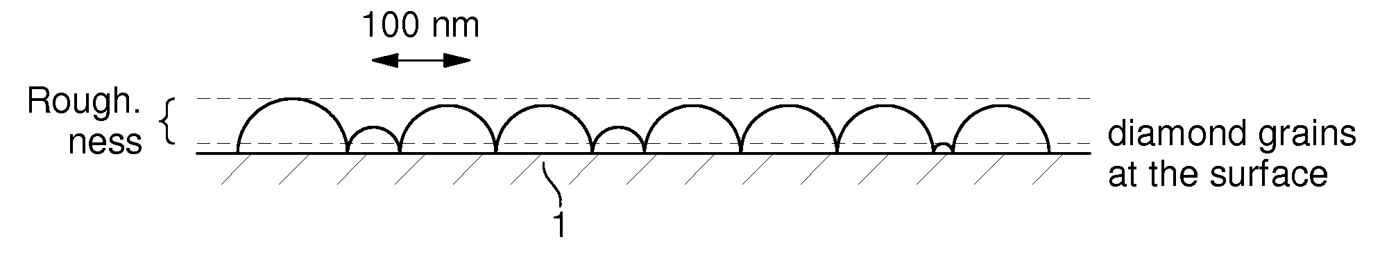
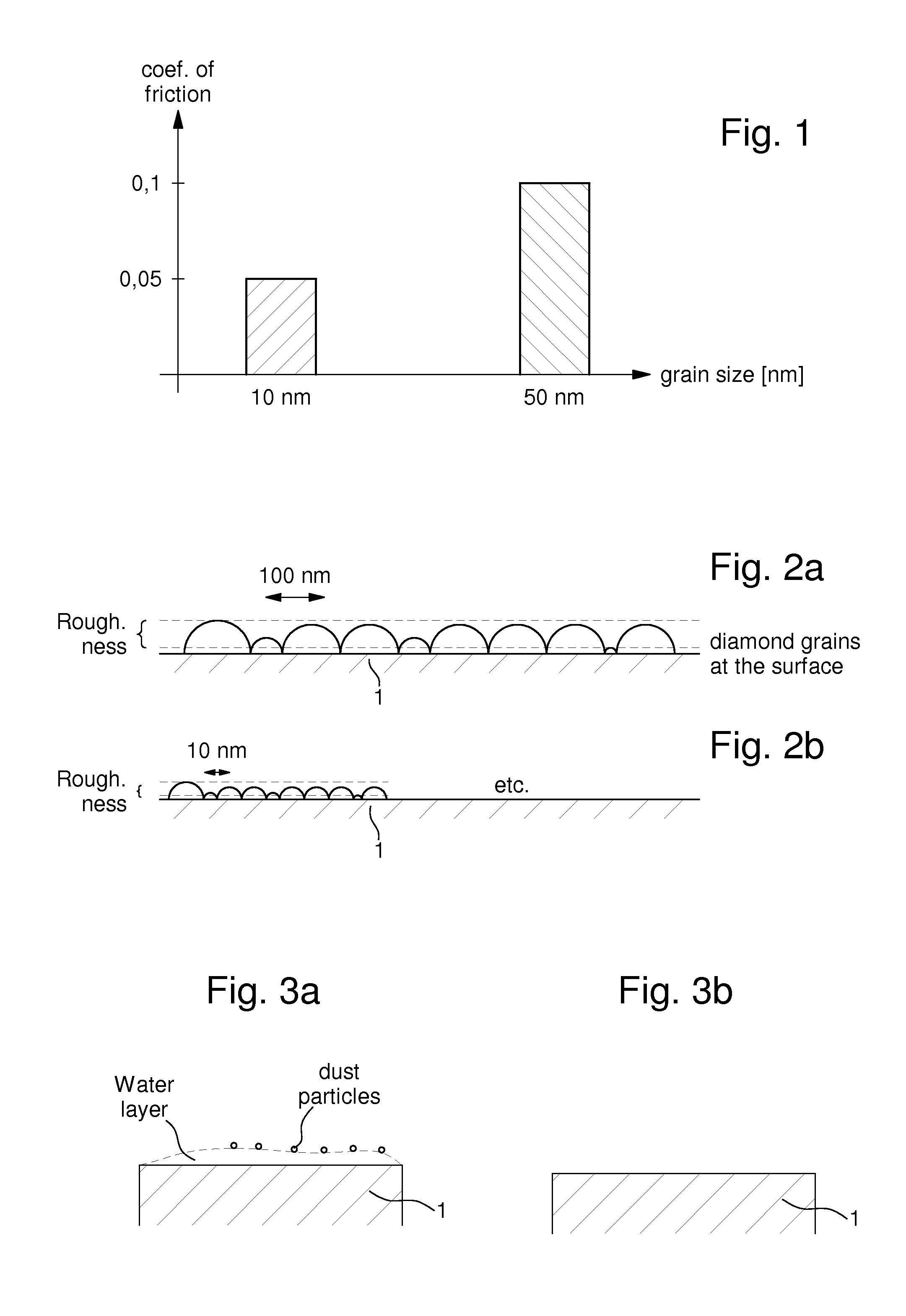
[0051]The invention presented is based on micromechanical components coated with NCD (nanocrystalline diamond) films of thicknesses between tens of nanometers and several micrometers. The crystals or grains have a size of a few nanometers, preferably less than 10 nanometers, as shown in FIG. 1. These diamond films comprise a coefficient of friction of less than 0.1, preferably less than 0.05, in special cases 0.03 or less. Such nanocrystalline diamond films are produced by a CVD (chemical vapour deposition) process. In an advantageous CVD process (discloses in AT399726B incorporated herein by reference) a carbon containing gas species (for example methane) is thermally activated and is deposited on a substrate as diamond (sp3-hybridised carbon), as graphite (sp2-hybridised carbon) as well as carbon hydrates or other carbon species (mixtures of sp2- and sp3-hybridised carbon). To obtain a pure diamond layer it is necessary to use a second gas: for instance hydrogen. The hydrogen gas ...


PUM

PropertyMeasurementUnit
Electrical conductivityaaaaaaaaaa
Electrical conductoraaaaaaaaaa
Hydrophobicityaaaaaaaaaa

Abstract

Method for coating micromechanical components of a micromechanical system, in particular a watch movement, comprising:
    • providing a substrate component to be coated;
    • providing said component with a diamond coating;
    • wherein said diamond coating conductivity is increased in order to reduce dust attraction by the coated component when used in said micromechanical system.
Corresponding micromechanical components and systems are also provided.

Description

FIELD OF THE INVENTION[0001]This invention relates to micromechanical parts with high tribological performances (low friction and wear) for application in mechanical systems and namely a method for coating micromechanical components of a micromechanical system, in particular a watch, for preventing the agglomeration of particles (debris and / or dust) on the functional areas of micromechanical components. The invention also relates to a micromechanical component for a micromechanical system, in particular a watch movement coated with said method. The invention can be used in micromechanical watch movements, in particular for the realisation of escapement wheels and pallets and other friction-relevant components.BACKGROUND TO THE INVENTION[0002]The technical demands relating to micromechanical components are growing: beside highest precision, the components need to provide highest energy efficiency in the mechanical system, long lifetime and complete abdication of lubricants insofar as...

Claims


Application Information

Patent Timeline
IPC IPC(8): B32B9/00H01B1/04C23C14/48B05D5/12C23C16/27
CPCB81B3/0008B81B2201/035B81C2201/112Y10T428/30C23C16/277C23C16/56G04D3/0074C23C16/27
Inventor STEINMULLER, DETLEFSTEINMULLER, DORISDREXEL, HERWIGGHODBANE, SLIMANERICHARD, DAVIDCUSIN, PIERRE
Owner THE SWATCH GRP RES & DEVELONMENT LTD
Why Eureka
Try Eureka