Direct exchange geothermal refrigerant power advanced generating system

a technology of geothermal refrigerant and advanced generating system, which is applied in the direction of machines/engines, mechanical equipment, light and heating apparatus, etc., can solve the problems of inability to access such inability to economically develop, and inability to meet the needs of high-level natural heat conditions, etc., to achieve enhanced flow rate, improved power production efficiency, and reduced boiling point/temperature

Active Publication Date: 2012-06-14
DEEP WELL POWER
View PDF7 Cites 27 Cited by
  • Summary
  • Abstract
  • Description
  • Claims
  • Application Information

AI Technical Summary

Benefits of technology

[0048]Additionally, a turbine / generator may sometimes be physically situated above the condenser, so that any refrigerant that might have phased changed within the turbine / generator into a liquid when the DX power generation system is operating primarily via vapor pressure, or that might not have phased changed out of a liquid within the turbine / generator when the DX power generation system is operating primarily via both gravity pressure and vapor phase change / expansion through the turbine / generator, will automatically drain into the condenser via gravity, absent the need for any liquid refrigerant pump. Also, via positioning the turbine / generator above the condenser, any refrigerant that might phase change from a vapor into a liquid within the larger vapor refrigerant transport line between the turbine / compressor and the condenser will also automatically fall via gravity into the condenser absent the need for any liquid refrigerant pump.
[0049]Lastly, as a means to control the liquid refrigerant flow at or near the bottom potion of the well, in any optional DX geothermal power generation system design, and especially in a DX geothermal power generation system design that produces turbine power primarily off of liquid refrigerant gravity pressure (with the liquid refrigerant being heated and vaporized within the well only to the extent necessary to get the refrigerant vapor out of the well and into the condenser at or near the surface), a refrigerant valve may be used. The refrigerant valve may include a tapered wedge, or the like, that may lower into, and / or to raise out of, a collar positioned within a liquid return line at or near the bottom of the liquid refrigerant transport line within the well. A cable, or the like, may be attached to the tapered wedge and extend to a cable fastening device provided at an accessible location situated at or above the ground surface, where the cable may be lowered into or raised out of the well by means of a winch or the like, thereby effectively lowering or raising the tapered wedge into and out of the collar, thereby adjusting the liquid refrigerant flow rate at or near the bottom of the well as desired.
[0050]The use of a refrigerant in the primary sub-surface circulating working fluid loop used for geothermal heat acquisition (instead of the use of water and / or a water and salt brine solution as historically used in traditional and conventional geothermal power production system designs), for enhanced power production efficiencies is a material geothermal power system design improvement. The use of a refrigerant, instead of the traditional use of water and / or a salt water for geothermal heat absorption, is more advantageous in a single loop power geothermal generation design, as disclosed herein, because the refrigerant has a lower boiling point / temperature than water (affording an enhanced flow rate), and / or because such a refrigerant can have a heavier weight than water (affording more gravitational power advantages). Simulation testing has shown that refrigerants to utilize in deep well geothermal power production applications, utilizing the designs, as explained herein, may included R-125 to a depth of about 27,000 feet; R-134A to a depth of about 30,000 feet; and CO2 to a depth beyond about 30,000 feet. With the exception that for both power generation and condensing purposes, the use of R-134A may generally still be more advantageous and preferable as a general all purpose refrigerant for use at all depths, both below and above 30,000 feet. Further, as one objective of the subject disclosure is to utilize the force of gravity for power production purposes, R-134A is heavier than water and is additionally advantageous in this regard. R-134A has a specific gravity of about 1.2, and therefore may provide a gravitational pressure advantage over water for purposes of the subject designs disclosed herein.

Problems solved by technology

(1) Dry steam power plants utilize steam (exiting wells drilled to a naturally occurring underground heat and steam production source) to drive a power generation turbine, with the turbine typically utilized to produce electricity. The areas in which a dry steam plant may be feasibly implemented, however, are relatively few.
(2) Flash steam geothermal power plants use water at very high pressure and temperature (i.e., at least approximately 182° C. or 360° F.) that is pumped under high pressure from typically very deep wells, to the surface. Upon reaching the surface, all or a portion of the very hot and high-pressure water is flashed into steam.
The geographic locations with conditions suitable to pressurize water to an extent great enough to produce viable amounts of electrical power, however, are not common and are typically not economically available.
(as noted above), and in some cases may need to exceed about 600° F., for economically viable power production, and system implementation and operation is costly to access such high-level natural heat conditions.
However such “hot spot” areas are relatively rare.
Also, known flash steam plants use water and therefore are limited to using the boiling / vaporization properties of water during system design.
Thus, most conventional geothermal power production plants require somewhat uniquely occurring circumstances to be economically viable, typically require at least two independent fluid loops (with 2-3 liquid pumps) and are not universally available.
Binary systems utilizing waste heat sources are more common, but either nuclear or fossil fuels are typically required as the primary heat source, both of which present environmental challenges.
Further, traditional Enhanced Geothermal Systems (EGS), using a binary geothermal system, have environmental challenges.
Regarding environmental challenges, EGS designs can create seismic activity when fracturing dry hot rocks between deep wells; can contribute to groundwater pollution when rock fracturing chemicals seep up into the aquifers; and lose significant quantities of water on a continuous basis in the open loop portion deep below the surface between the supply and return wells.

Method used


Image

  • Direct exchange geothermal refrigerant power advanced generating system
  • Direct exchange geothermal refrigerant power advanced generating system
  • Direct exchange geothermal refrigerant power advanced generating system

Examples


first embodiment

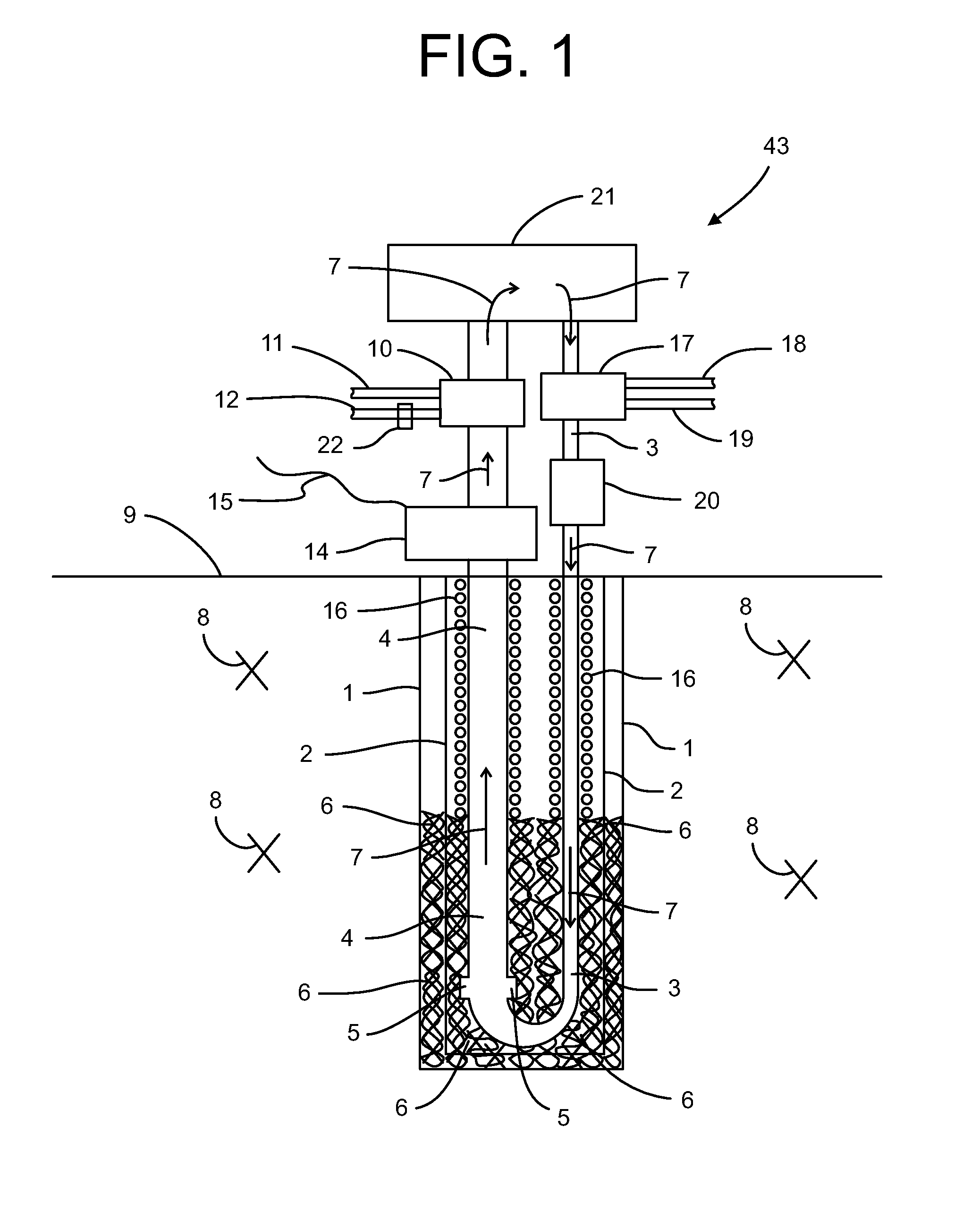
[0059]Referring now to the drawings in detail, where like numerals refer to like parts or elements, FIG. 1 is a side view of a direct exchange geothermal power generating system 43 constructed according to the present disclosure based upon refrigerant (indicated by directional flow arrows 7) being heated, phase changed into a vapor, and pressurized by the naturally occurring geothermal temperature within a well 1. Here, power is primarily derived via pressurized refrigerant 7 vapor driving a turbine / generator 14.

[0060]FIG. 1 shows a side view of the well 1 within a sub-surface environment 8, which may be at least one of ground, earth, rock, magma, and water. An optional heat conductive casing 2 formed of steel, metal, or other heat conductive material may be inserted into the well 1. A heat conductive fill material 6 may be disposed between the interior wall of the well 1 and the exterior wall of the casing 2 to facilitate geothermal heat transfer. When all or a portion of the well ...

second embodiment

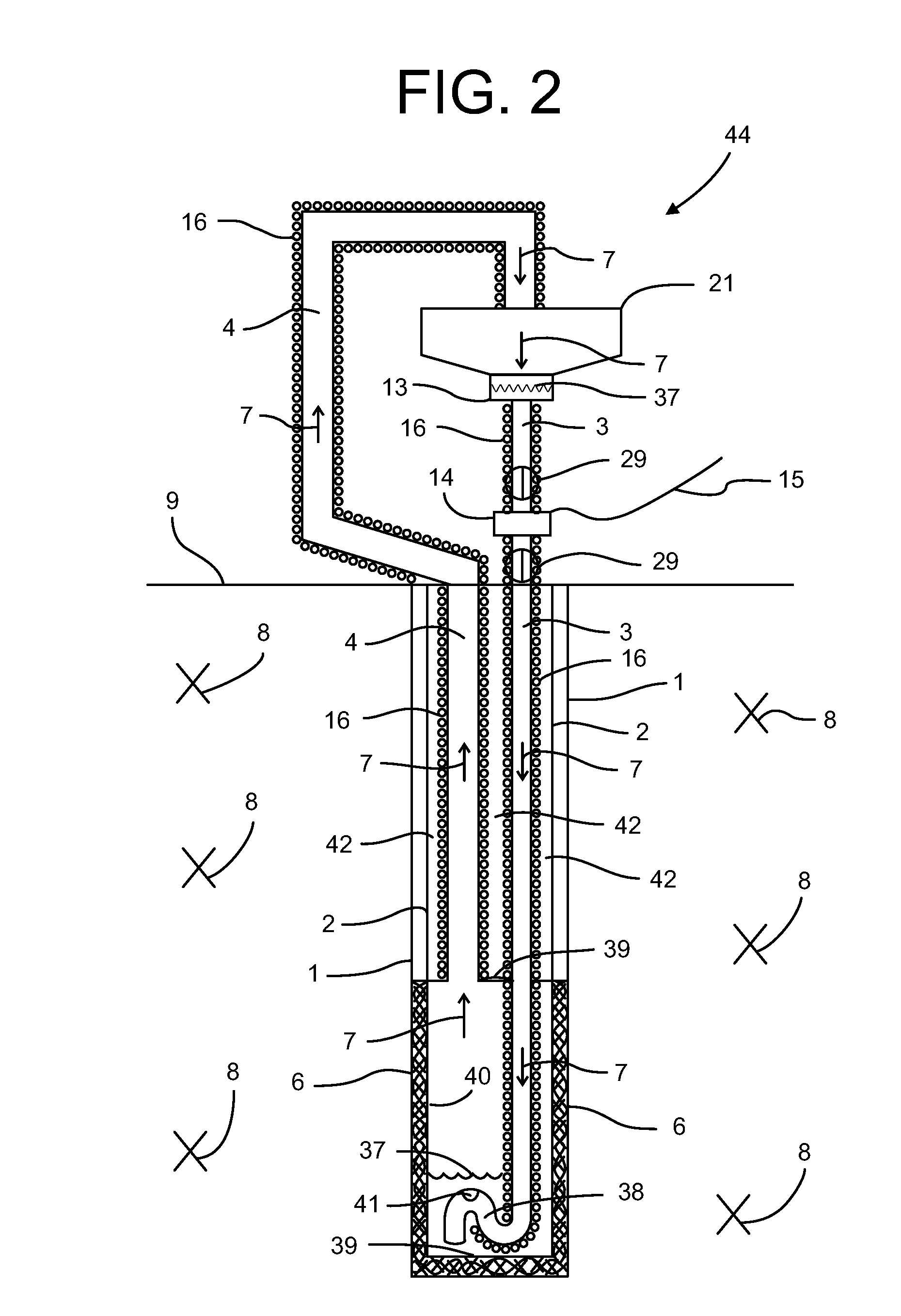
[0073]a direct exchange geothermal power generating system 44 is illustrated in FIG. 2. This system 44 uses a refrigerant 7 that is heated and undergoes a phase change from liquid into vapor by the naturally occurring geothermal temperature within a deep well 1, and generates power primarily from the gravitational pressure of a column of liquid refrigerant within the deep well 1. The heated, vapor refrigerant produced at the bottom of the well 1 naturally travels upward from the well to a condenser 21 without the need of a pump.

[0074]The well 1 is formed in a sub-surface environment 8 which may include at least one of ground, earth, rock, magma, and / or water. An optional heat conductive casing 2, which may be formed of steel, metal, or other heat conductive material, is disposed within the well 1. A heat conductive fill material 6 is disposed between the interior wall of the well 1 and the exterior wall of the casing 2 in the lower portion of the well 1 to effect and promote geother...

third embodiment

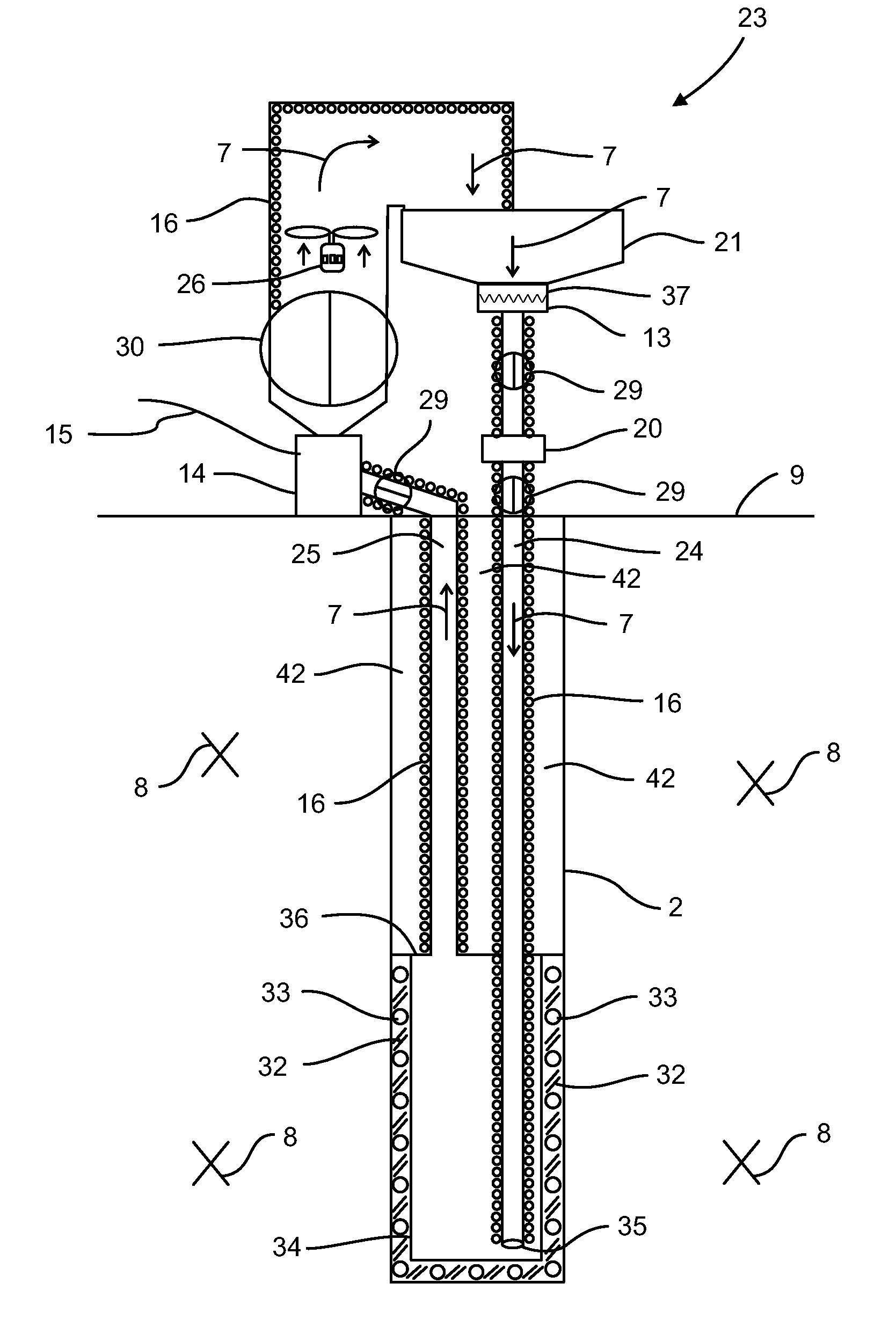
[0088]FIG. 3 illustrates a direct exchange geothermal power generating system 23 constructed according to the present disclosure. In this embodiment, the sub-surface environment 8 acts as the primary heat supply for the refrigerant (indicated by directional flow arrows 7) within a closed refrigerant transport loop. The loop primarily includes a denser liquid refrigerant transport return line 24 (for clarification, the return line 24 construction itself is not denser, rather, the liquid refrigerant 7 within the return line 24 is cooler and denser) and a less-dense liquid refrigerant transport supply line 25 (for clarification, the supply line 25 construction is itself not less-dense, rather, the liquid refrigerant 7 within the supply line 25 is warmer, expanded, and less dense), together with a turbine / generator 14 and a condenser 21.

[0089]In the embodiment of FIG. 3, the system 23 operates primarily on both liquid refrigerant gravitational pressure and refrigerant phase change / expan...


PUM


Abstract

A single closed loop direct exchange geothermal power production system that utilizes a refrigerant working fluid in at least one of three primary designs to generate electrical power from deep wells: with a first version of a direct exchange geothermal power generating system operating primarily on refrigerant vapor pressure; with a second version of a direct exchange geothermal power generating system operating primarily on liquid refrigerant gravitational pressure; and with a third version of a direct exchange geothermal power generating system operating primarily on both liquid refrigerant gravitational pressure and refrigerant phase change/expansion from a liquid to a vapor state.

Description

FIELD OF THE DISCLOSURE[0001]The present disclosure relates to direct exchange geothermal power generating systems. Here, geothermal power production is based on the pressure and / or phase change of a refrigerant fluid, or the like, created via direct heat exchange within a single closed refrigerant transport loop, utilizing a sub-surface well to access naturally occurring geothermal heat, as opposed to conventional geothermal power production designs that are traditionally based on circulating, or utilizing, at least one water loop circulating within a geothermal heat source to acquire heat, and then exchanging such heat with another separate and secondary power generating refrigerant fluid loop. Most common conventional geothermal system power production designs are termed binary systems, and typically require at least three primary heat exchange loops and at least two, and typically three, fluid circulating pumps.[0002]As used herein, a “direct exchange” geothermal power generatin...

Claims


Application Information

Patent Timeline
Patent Type & Authority Applications(United States)
IPC IPC(8): F03G7/00
CPCY02E10/10F03G7/04F24T10/15F24T10/30F24T10/40
Inventor WIGGS, B. RYLANDTHOMS, RICHARD
Owner DEEP WELL POWER
Why Eureka
Try Eureka