Infrared transmission filter and imaging device

a technology of infrared transmission filter and imaging device, which is applied in the direction of lighting and heating apparatus, instruments, radioation controlled devices, etc., can solve the problems of cut-off characteristics, inability to meet the requirements of a size reduction application, and inability to adjust the angle of incident, etc., to achieve excellent optical characteristics, insufficient size and thinness, excellent infrared permselectivity

Active Publication Date: 2012-06-14
ASAHI GLASS CO LTD
View PDF19 Cites 68 Cited by
  • Summary
  • Abstract
  • Description
  • Claims
  • Application Information

AI Technical Summary

Benefits of technology

[0021]In accordance with the present invention, it is possible to provide an infrared transmission filter which is inexpensive, can be made sufficiently smaller and thinner, has no incident angle dependence unlike reflection filters and has an extremely excellent infrared permselectivity. In accordance with the present invention, it is also possible to provide an imaging device including such an IR transmission filter and having an excellent optical characteristics.

Problems solved by technology

However, such reflection filters, which are constituted by a glass base material having a multilayer dielectric film vapor-deposited thereon, have a problem of incident angle dependence in that the cut-off characteristics varies according to the incident angle of visible light.
Further, visible light absorbing glass filters are not suited for an application where size reduction and weight reduction are needed, such as cameras, because of having a large weight and difficulty in thickness reduction.
Furthermore, such visible light absorbing glass filters have a problem in that they are expensive.
However, such type of existing filters are insufficient in permselectivity for infrared light closer to visible light.
Specifically, such type of existing filters have a poor cut-off characteristics for light in a wavelength range of from 730 to 830 nm.
For this reason, this type of existing filters have not been put into practice because of having a small S / N ratio in e.g. an application where an object is irradiated with light having a wavelength of from 830 to 850 nm, and the light reflected from the object is captured by an infrared camera.

Method used


Image

  • Infrared transmission filter and imaging device
  • Infrared transmission filter and imaging device
  • Infrared transmission filter and imaging device

Examples


first embodiment

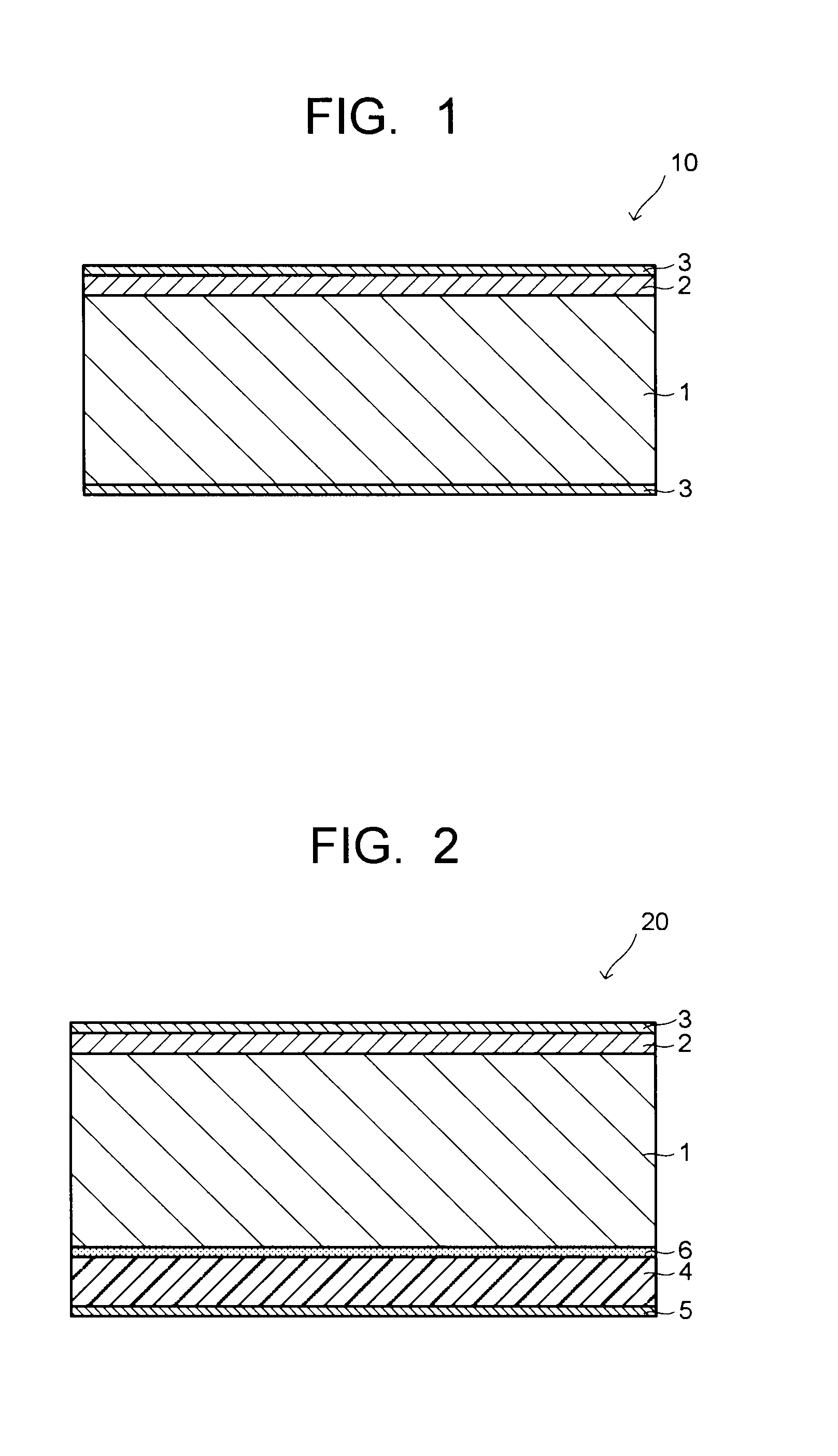
[0047]FIG. 1 is a schematic cross-sectional view showing a portion of the IR transmission filter according to a first embodiment of the present invention. As shown in FIG. 1, the IR transmission filter 10 according to this embodiment includes an IR transmission base material 1, an S-IR absorbing film 2 formed on one side of the IR transmission base material and containing an nIR absorbent, and an antireflection film 3 formed on each of the other side of the IR transmission base material and the side of the S-IR absorbing film remote from the IR transmission base material.

[0048]The IR transmission base material 1 is constituted by a transparent resin containing a visual light absorbent, which absorbs light in a visible wavelength range. The wording “transparent resin” refers to a synthetic resin, which transmits at least light in an IR wavelength region. The transparent resin may be, for example, an acrylic resin, a styrene resin, an ABS resin, an AS resin, a polycarbonate resin, a p...

second embodiment

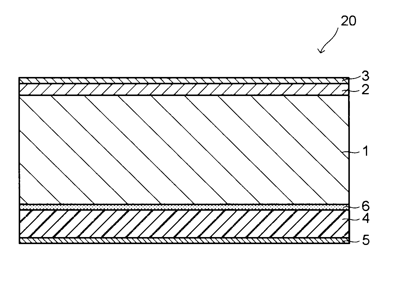
[0072]FIG. 2 is a schematic cross-sectional view showing a portion of the IR transmission filter according to a second embodiment of the present invention. In order to avoid duplicate explanation with respect to this embodiment and its subsequent embodiments, explanation of the features common to the first embodiment will be omitted, and the different features will be mainly described.

[0073]As shown in FIG. 2, in the IR transmission filter 20 according to the second embodiment, a glass base material 4, which has an L-IR reflection film 5 of a multilayer dielectric film formed on one side, is bonded through an adhesive 6, to one side of an IR transmission base material 1 (a side opposite to a side with an S-IR absorbing film 2 being formed thereon) such that the L-IR reflection film 5 faces outward.

[0074]The L-IR reflection film 5 is a film, which has a function of reflecting and cutting off light on a long wavelength side of the transmission wavelength band, such as a film wherein t...

third embodiment

[0083]FIG. 4 is a schematic cross-sectional view showing the IR transmission filter according to a third embodiment of the present invention.

[0084]As shown in FIG. 4, in the IR transmission filter 40 according to the third embodiment, a glass base material 4, which has an S-IR reflection film 7 of a multilayer dielectric film formed on one side, is bonded, through an adhesive 6, to the other side of the IR transmission base material 1 (side opposite to a side with an S-IR absorbing film 2 being formed thereon) such that the S-IR reflection film 7 faces outward.

[0085]The S-IR reflection film 7 is configured to reduce incident angle dependence, sacrificing a cut-off effect to light in a visible light range of a usual visible light reflection film as described later, and the reflection wavelength band to light vertically entering ranges 730 to 810 nm, for example. The S-IR reflection film 7 may be formed by alternating layering low refractive index dielectric layers and high refractive...


PUM


Abstract

There are provided an infrared transmission filter, which is inexpensive, is capable of being sufficiently made lighter and thinner, has no incident angle dependency, and is excellent in permselectivity for infrared light, and an imaging device, which employs such an infrared transmission filter.
An infrared transmission filter 10 includes an infrared transmission base material 1 selectively transmitting light in an infrared wavelength range; and a short wavelength side infrared absorbing film 2 formed on one side of the infrared transmission base material 1 and containing a near-infrared absorbent having an optical absorption edge on a short wavelength side of a transmission wavelength band of the infrared transmission base material. An imaging device includes the infrared transmission filter 10.

Description

BACKGROUND OF THE INVENTION[0001]1. Field of the Invention[0002]The present invention relates to an infrared transmission filter and an imaging device, such as an infrared camera employing the same.[0003]2. Discussion of Background[0004]Devices, which utilize light in a specific infrared wavelength range of from 0.7 μm to 2.5 μm (hereinbelow, also referred to as “infrared light”), for example, infrared remote controllers for home electric appliances, such as TV sets, audio products and air conditioners, infrared communication for exchange of information between cellular phones or personal computers, and infrared cameras for night photography or for security purposes, or motion sensors, have increased for recent years. This trend has increased the demand for filters, which cut off light in a visible wavelength range (hereinbelow, also referred to as “visible light”) serving as noise in these devices, and which selectively transmit only infrared light. Further, such infrared cameras a...

Claims


Application Information

Patent Timeline
Patent Type & Authority Applications(United States)
IPC IPC(8): H01L27/146G02B5/28G02B5/22
CPCG02B5/208H01L27/14621G02B5/22
Inventor KAKIUCHI, TOSHIMASAHASEGAWA, MAKOTOMORI, MASAHIRO
Owner ASAHI GLASS CO LTD
Why Eureka
Try Eureka