Laser projector

a laser projector and projector technology, applied in projectors, color television details, instruments, etc., can solve the problems of large required area, limited color reproduction range of lamps, short life of lamps, etc., and achieve the effect of low speckle noise and high luminan

Inactive Publication Date: 2012-06-14
PANASONIC CORP
View PDF5 Cites 31 Cited by
  • Summary
  • Abstract
  • Description
  • Claims
  • Application Information

AI Technical Summary

Benefits of technology

[0017]An object of the present invention is to provide a safe and compact laser proje

Problems solved by technology

The lamp has, however, a short life.
A color reproduction range of the lamp is also limited.
In addition, there are drawbacks of a large required area and inefficient light utilization of the lamp.
The laser projector has a problem about speckle noise.
The speckle noise results from high coherence of the laser beam.
The former speckle noise in the diffracted field may become problematic in an exposure device and an illumination optical system.
Both speckle noises in the diffracted field and the image field become problematic in the laser projector.
Accordingly, such a laser projector is unsuitable for the miniaturization of the optical system.
In addition, the disclosed laser projector achieves an insufficient level in te

Method used


Image

  • Laser projector
  • Laser projector
  • Laser projector

Examples


first embodiment

(Laser Projector)

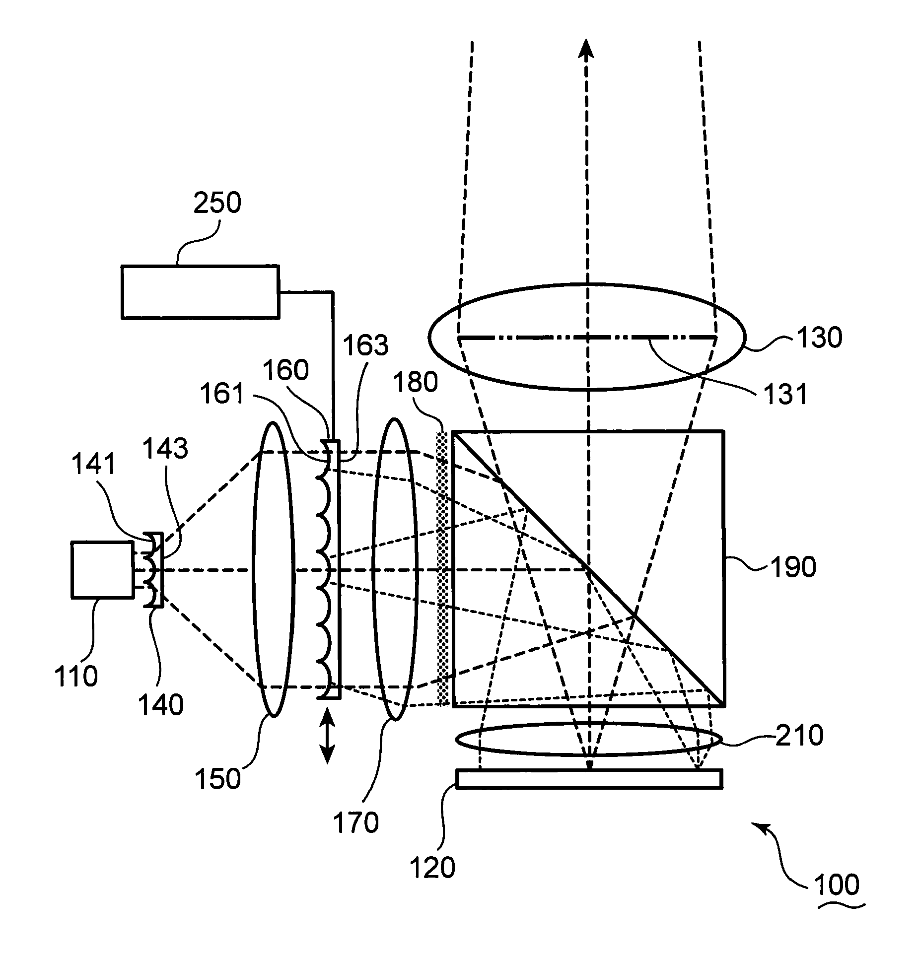
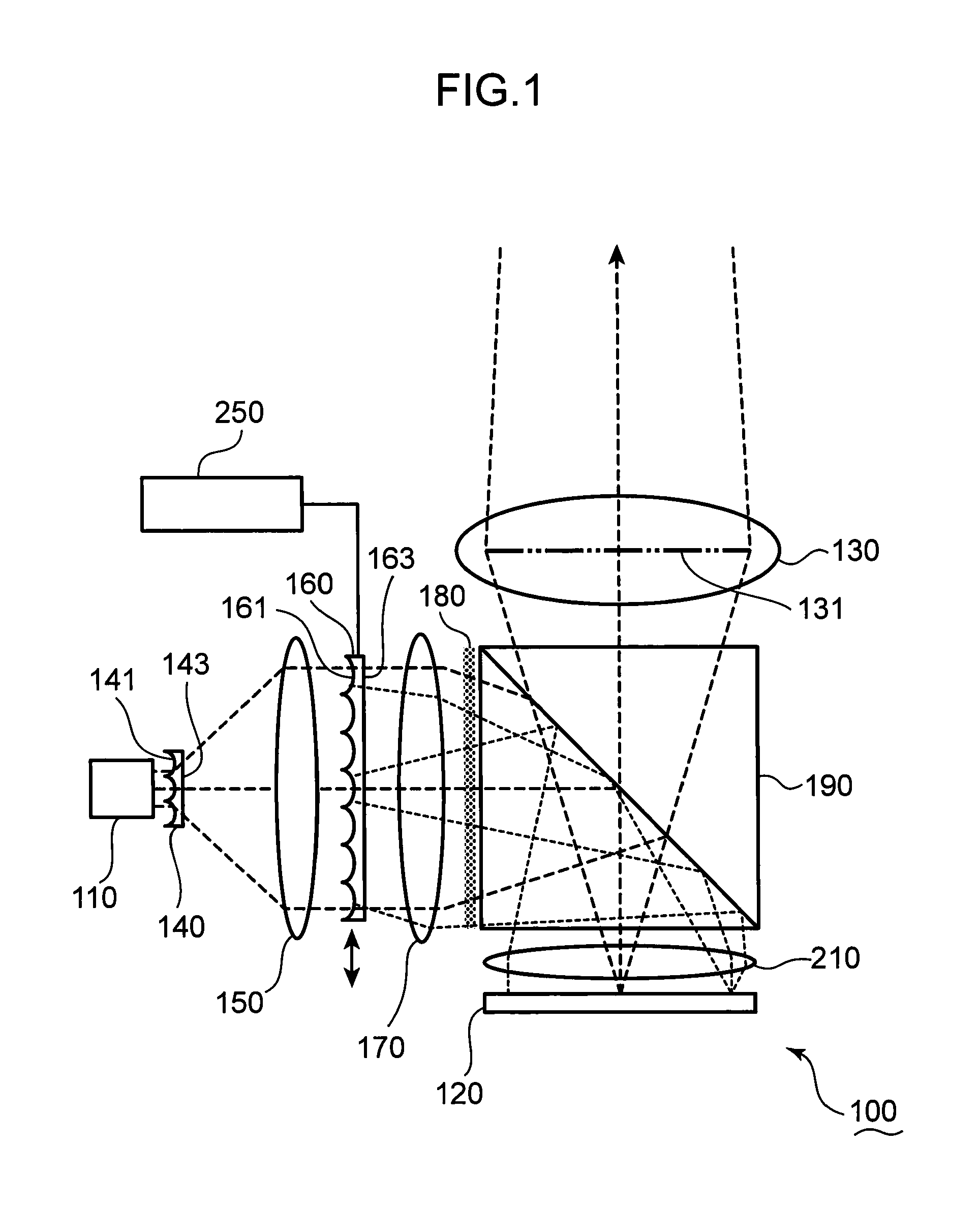
[0040]FIG. 1 is a schematic view of a laser projector 100 according to the first embodiment. The laser projector 100 is described with reference to FIG. 1.

[0041]The laser projector 100 includes: a laser source 110 which emits a laser beam; a spatial light modulator 120 which modulates the laser beam to generate image light; and a projector lens 130 from which the image light is emitted. In this embodiment, the laser source 110 is exemplified as the laser source section.

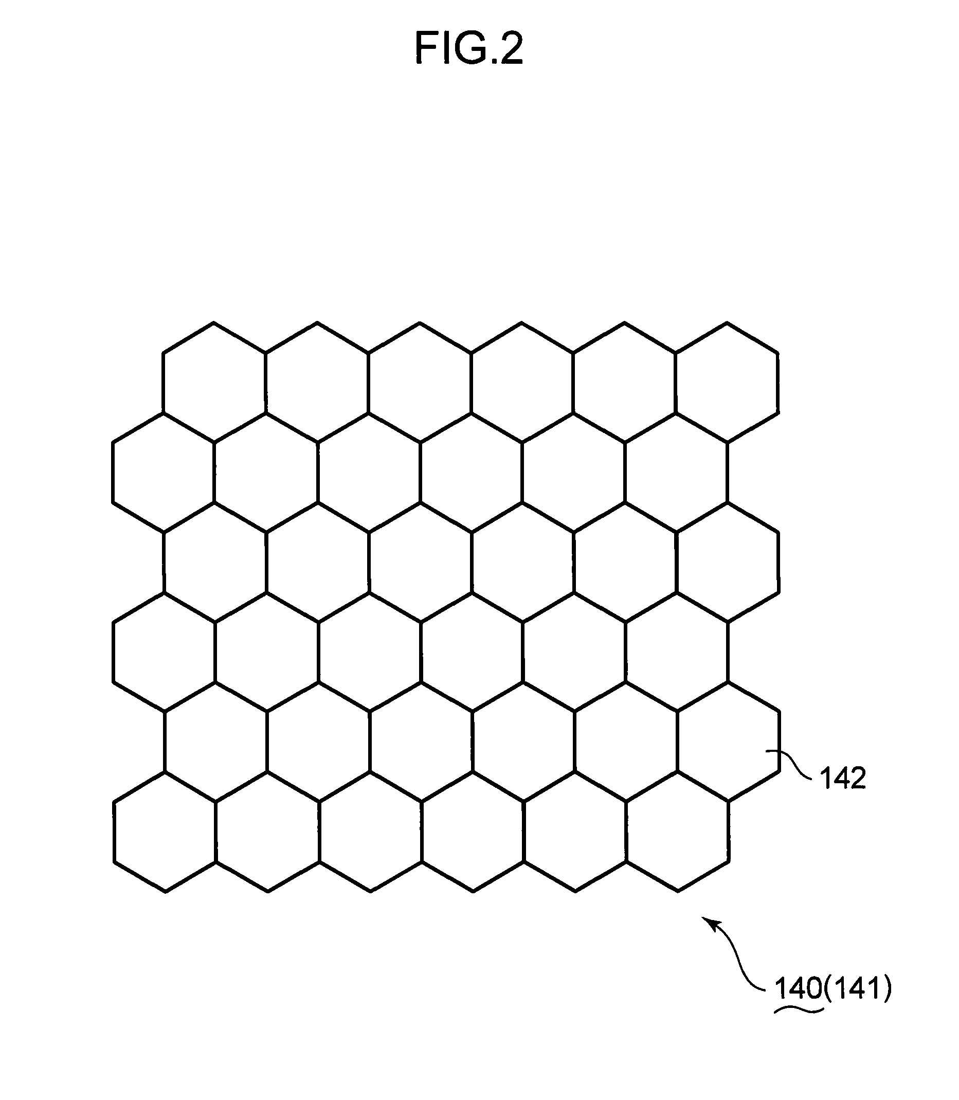
[0042]An exit pupil 131 of the projector lens 130 is depicted by the thick chain line in FIG. 1. The laser projector 100 further includes a pupil uniformizer 140, which makes a light intensity distribution uniform at the exit pupil 131 of the projector lens 130. The pupil uniformizer 140 includes an incident end surface 141 to which the laser beams emitted from the laser source 110 are incident.

[0043]FIG. 2 is a schematic view of a lens pattern formed on the incident end surface 141 of the pupil unifo...

second embodiment

[0110]FIG. 7 is a schematic view of a laser projector 100A according to the second embodiment. The laser projector 100A is described with reference to FIG. 7. It should be noted that the similar symbols and numerals are assigned to the similar components described in the first embodiment. Descriptions about the similar components are omitted.

[0111]Like the laser projector 100 of the first embodiment, the laser projector 100A includes the pupil uniformizer 140, the collimator 150, the condenser lens 170, the light diffuser 180, the PBS 190, the field lens 210, the projector lens 130 and the actuator 250. The laser projector 100A further includes a red laser source 110r, which emits a red laser beam, a green laser source 110g, which emits a green laser beam, and a blue laser source 110b, which emits a blue laser beam. In this embodiment, the red, green and blue laser sources 110r, 110g, 110b are exemplified as the laser source section.

[0112]The laser projector 100A further includes co...

third embodiment

[0128]FIG. 8 is a schematic view of a laser projector 100B according to the third embodiment. The laser projector 100B is described with reference to FIGS. 2 and 8. It should be noted that the similar symbols and numerals are assigned to the similar components, which are described in the first and second embodiments. The descriptions about these similar components are omitted.

[0129]Like the laser projector 100 of the first embodiment, the laser projector 100B includes the pupil uniformizer 140, the collimator 150 and the actuator 250. Like the laser projector 100A of the second embodiment, the laser projector 100B further includes the red, green and blue laser sources 110r, 110g, 110b, the collimator 111 and the multiplex prism 112.

[0130]The laser projector 100B further includes a spatial light modulator 120B which modulates the laser beams to generate the image light. In this embodiment, DMD (Digital Micro-mirror Device) is used as the spatial light modulator 120B. The laser projec...


PUM


Abstract

There is provided a laser projector, including: a laser source section for emitting laser beams; a spatial light modulator which modulates the laser beams to generate image light; a projector lens from which the image light is emitted; a beam shaper which shapes the laser beams into a shape of the spatial light modulator; and a pupil uniformizer which makes a light intensity distribution uniform at an exit pupil of the projector lens, wherein the pupil uniformizer is situated between the laser source section and the beam shaper.

Description

TECHNICAL FIELD[0001]The present invention relates to a laser projector which uses laser as a light source.BACKGROUND OF THE INVENTION[0002]Recently, a projector, which projects images on various projection surfaces such as a screen, has been widely used. A lamp is generally used as a light source of the projector. The lamp has, however, a short life. A color reproduction range of the lamp is also limited. In addition, there are drawbacks of a large required area and inefficient light utilization of the lamp.[0003]It is attempted that a laser source is used as the light source of the projector, in order to solve the aforementioned problems. The laser source has a longer life and a stronger directivity than the lamp. Accordingly, it is likely that the laser source efficiently utilizes light. The laser source is monochromatic to achieve a large color reproduction range. Therefore, the projector utilizing the laser source may display vivid images.[0004]If a smaller laser source than a ...

Claims


Application Information

Patent Timeline
IPC IPC(8): G03B21/14
CPCG02B13/007G02B27/0933G02B27/141G02B27/48H04N9/3164G03B21/2006G03B21/2033G03B21/208H04N9/3161G03B21/14
Inventor MIZUSHIMA, TETSUROITOH, TATSUOKASAZUMI, KENICHINAKAYAMA, KENJI
Owner PANASONIC CORP
Why Eureka
Try Eureka