Method of making carbide derived carbon with enhanced porosity and higher purity
a technology of porous carbon and carbide, which is applied in the field of making high purity porous carbon, can solve the problem that the material does not show high performance in absolute terms
- Summary
- Abstract
- Description
- Claims
- Application Information
AI Technical Summary
Problems solved by technology
Method used
Image
Examples
example 1
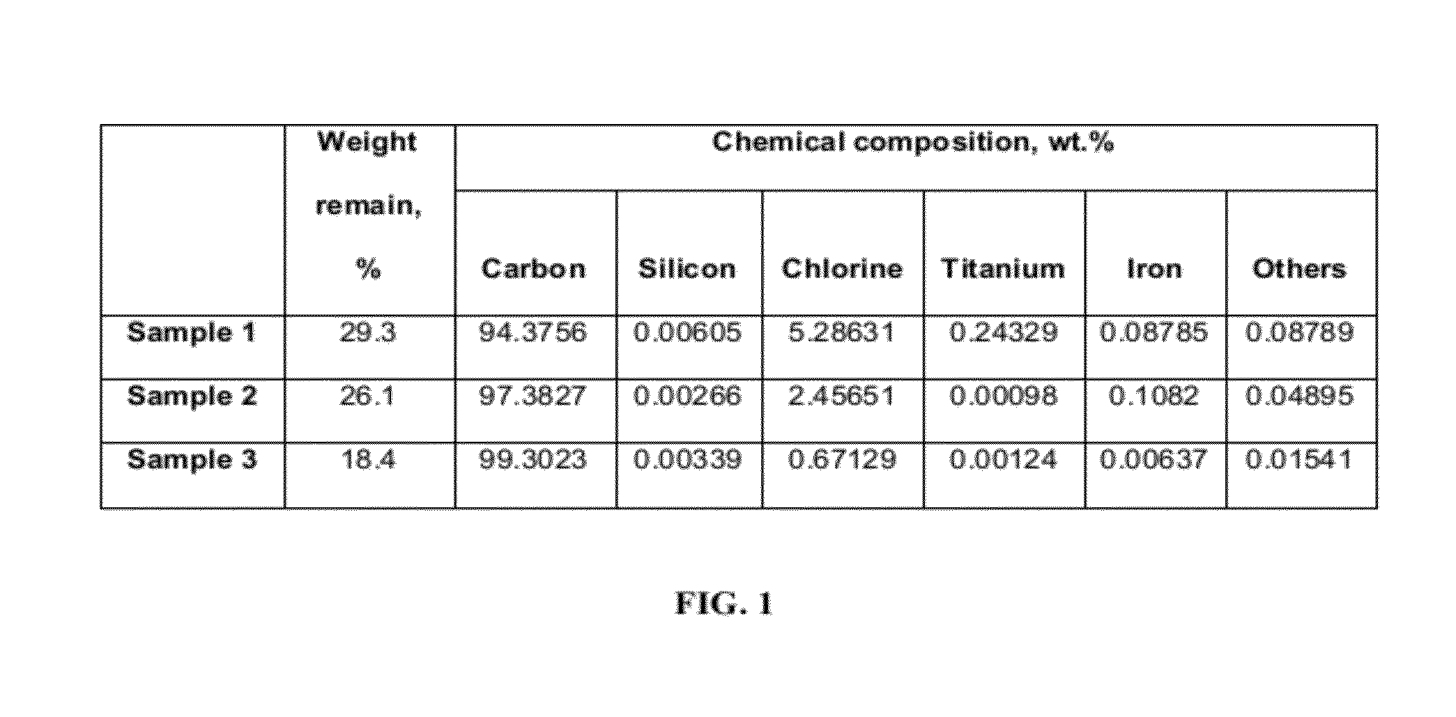
[0038]Three CDC samples (Sample 1, 2 and 3) (FIG. 1) were produced by chlorinating titanium carbide (TiC) powder precursor of particle size of <5 μm.
[0039]Sample 1 was produced by chlorination at 400° C. for 6 hours followed by argon purge at 400° C. for 30 minutes. The sample was cooled to room temperature under argon purge.
[0040]Sample 2 was produced by treating titanium carbide powder at 400° C. for 6 hours in chlorine followed by argon treatment at 1050° C. for 4 hours. The sample was cooled to room temperature under argon purge.
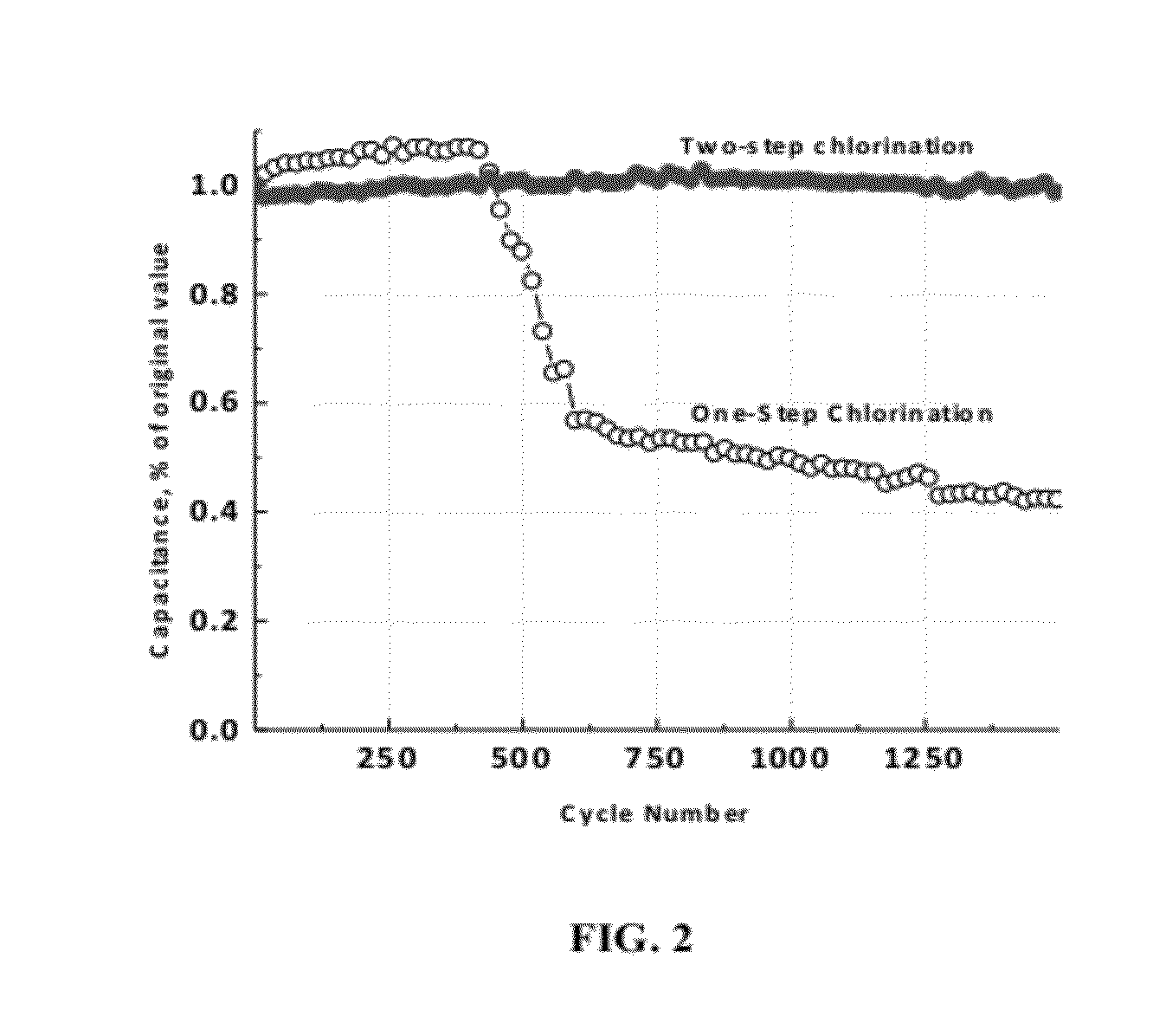
[0041]Sample 3 was produced by two-step chlorination. The conditions for first and second step chlorination were 400° C. for 6 hours, and 1050° C. for 2 hours, respectively. The furnace was heated in argon environment between first and second chlorination step. An argon purge of 4 hours at 1050° C. followed the second step chlorination.
[0042]Sample 1, Sample 2 and Sample 3 were prepared using the same experimental setup and the cooling and heating rate w...
example 2
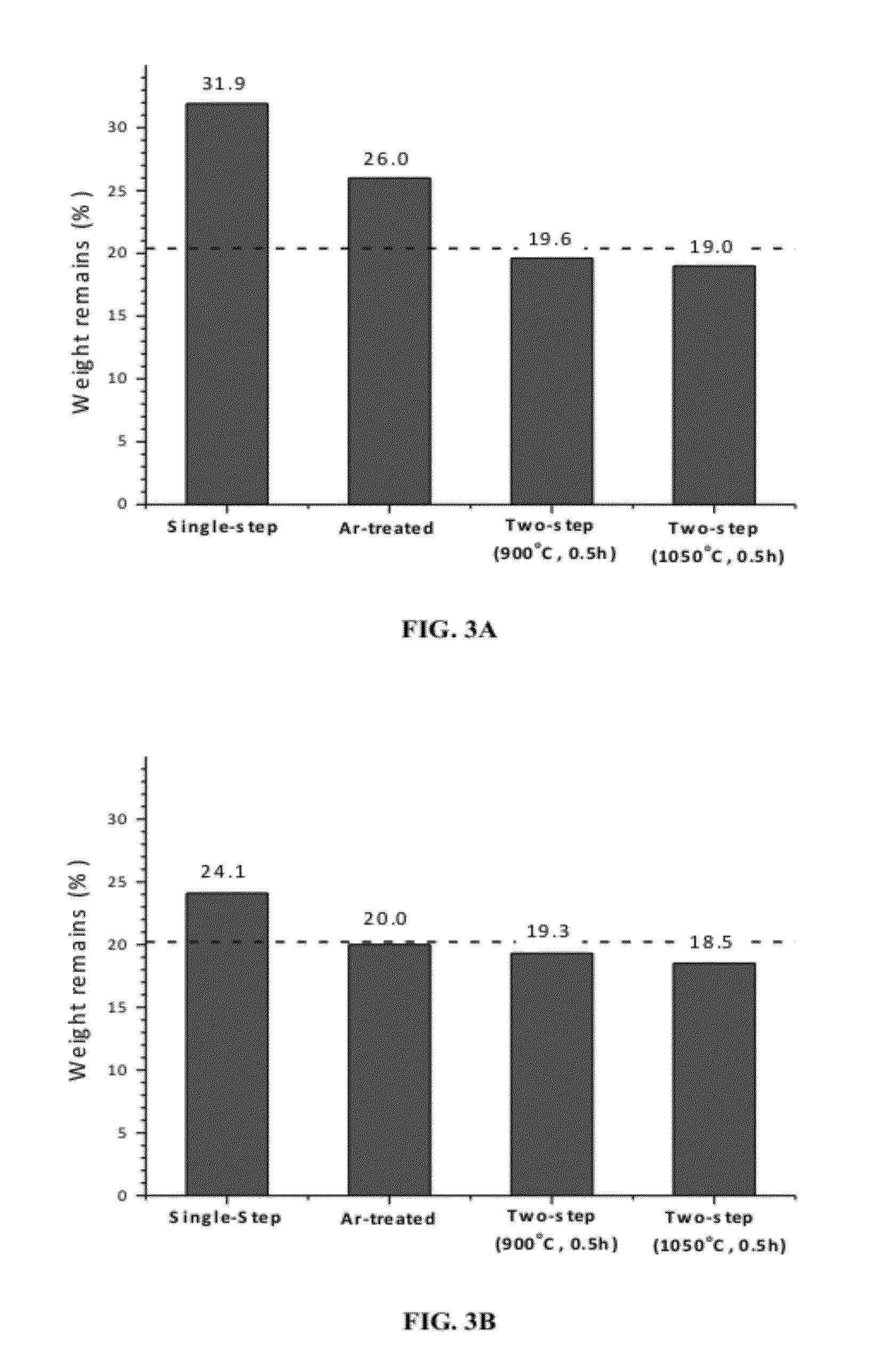
[0046]CDC powder was produced by chlorinating metal carbide powder precursor in a vessel at different chlorination. As can be seen in FIG. 3D and FIG. 3E, the weight remain, % decreases with chlorination temperature. Further, the weight remain, % for carbon made from titanium carbide was less than the theoretical value of 20.04% (FIG. 3C) for the conversion of titanium carbide to carbon suggesting that there is some degree of etching of carbon by chlorine. This clearly suggests that carbon is being etched by chlorine at temperatures above 800° C. contrary to the general belief that carbon is inert to chlorine. Thermodynamically, formation of CCl4 (carbon tetrachloride) is feasible by chlorination of metal carbide but only at low chlorination temperatures (preferably below 600° C.). Graphite (vendor: Sigma-Aldrich, purity: 99.99%, particle size: 95%, particle size: 3B, 3C). Argon treatment resulted in decrease in weight remain which can be explained by the decrease in chlorine level ...
example 3
[0047]Two samples (Sample A and Sample B) (FIG. 4) were produced by chlorinating titanium carbide (TiC) powder precursor of particle size of 3 / g to 0.54 cm3 / g and 1125 m2 / g to 1245 m2 / g by using a two-step chlorination route. The surface area was calculated using Brunauer-Emmet-Teller. It is clear from this example that using two-step chlorination, one can further tailor the porosity (pore size, surface area, pore volume) of CDCs.
PUM
| Property | Measurement | Unit |
|---|---|---|
| temperature | aaaaa | aaaaa |
| temperature | aaaaa | aaaaa |
| time | aaaaa | aaaaa |
Abstract
Description
Claims
Application Information
 - R&D
- Intellectual Property
- Life Sciences
- Materials
- Tech Scout
- Unparalleled Data Quality
- Higher Quality Content
- 60% Fewer Hallucinations
Browse by: Latest US Patents, China's latest patents, Technical Efficacy Thesaurus, Application Domain, Technology Topic, Popular Technical Reports.
© 2025 PatSnap. All rights reserved.Legal|Privacy policy|Modern Slavery Act Transparency Statement|Sitemap|About US| Contact US: help@patsnap.com


