
Multi-Electrode Energy Delivery Device and Method of Using the Same

a multi-electrode, energy delivery technology, applied in the field of medical devices, can solve the problems of incomplete treatment, system malfunction, cell death, etc., and achieve the effect of uniform ablation of tissu

Active Publication Date: 2012-06-14
ANGIODYNAMICS INC
View PDF2 Cites 59 Cited by
  • Summary
  • Abstract
  • Description
  • Claims
  • Application Information

AI Technical Summary

Benefits of technology

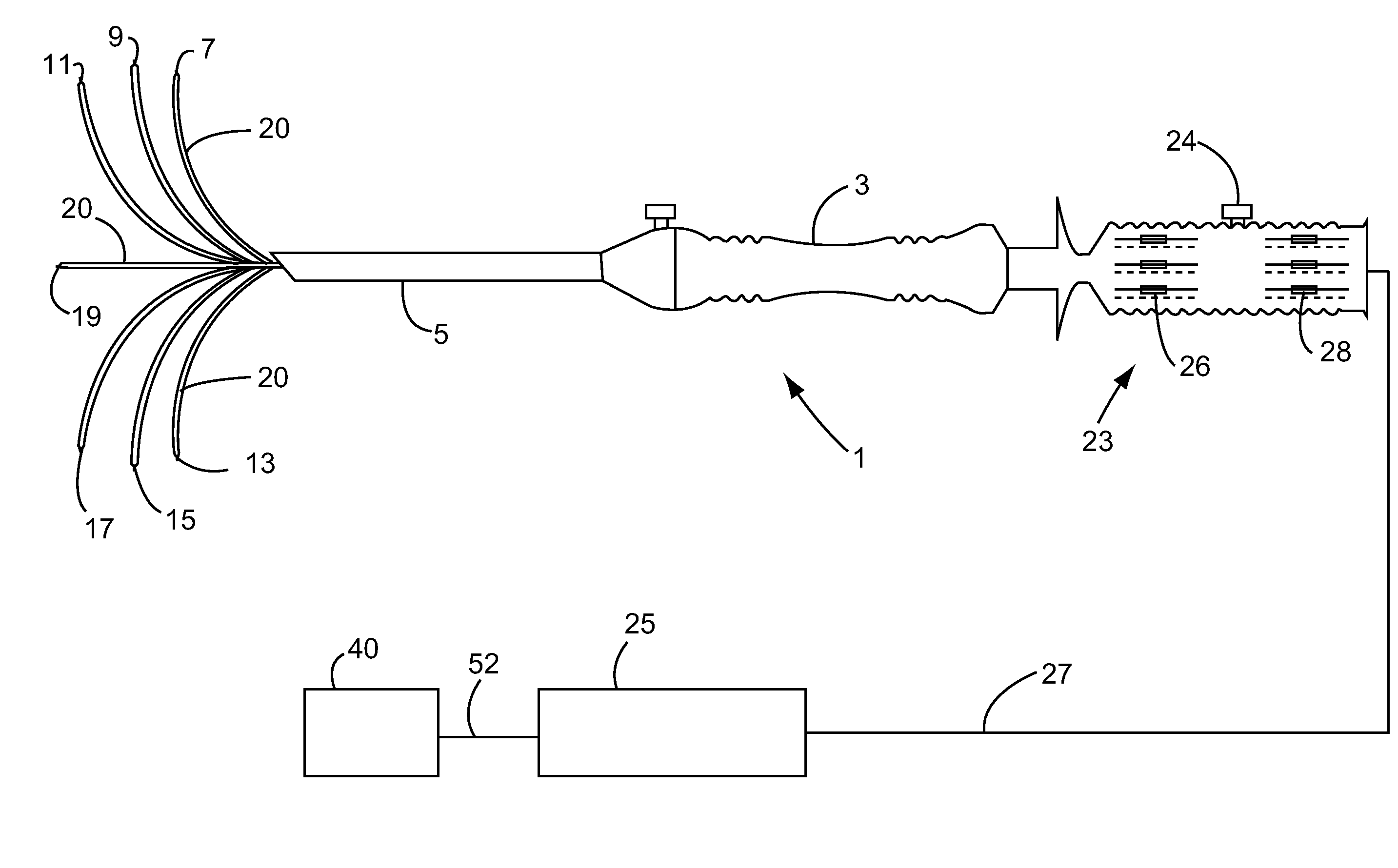
[0008]Electrode arrays with an umbrella-like profile achieves larger, more spherical ablations with a single puncture. In this type of probe, two or more outwardly curving tines (electrodes) are placed within the tumor and RF energy flows from each active tine or electrode in the array towards a grounding pad on the patient's skin. Although the array design allows for larger ablations with a single device and single puncture site, the energy dispersion is less efficient than bipolar designs because of the greater distance between the positive electrodes and negative ground pad.
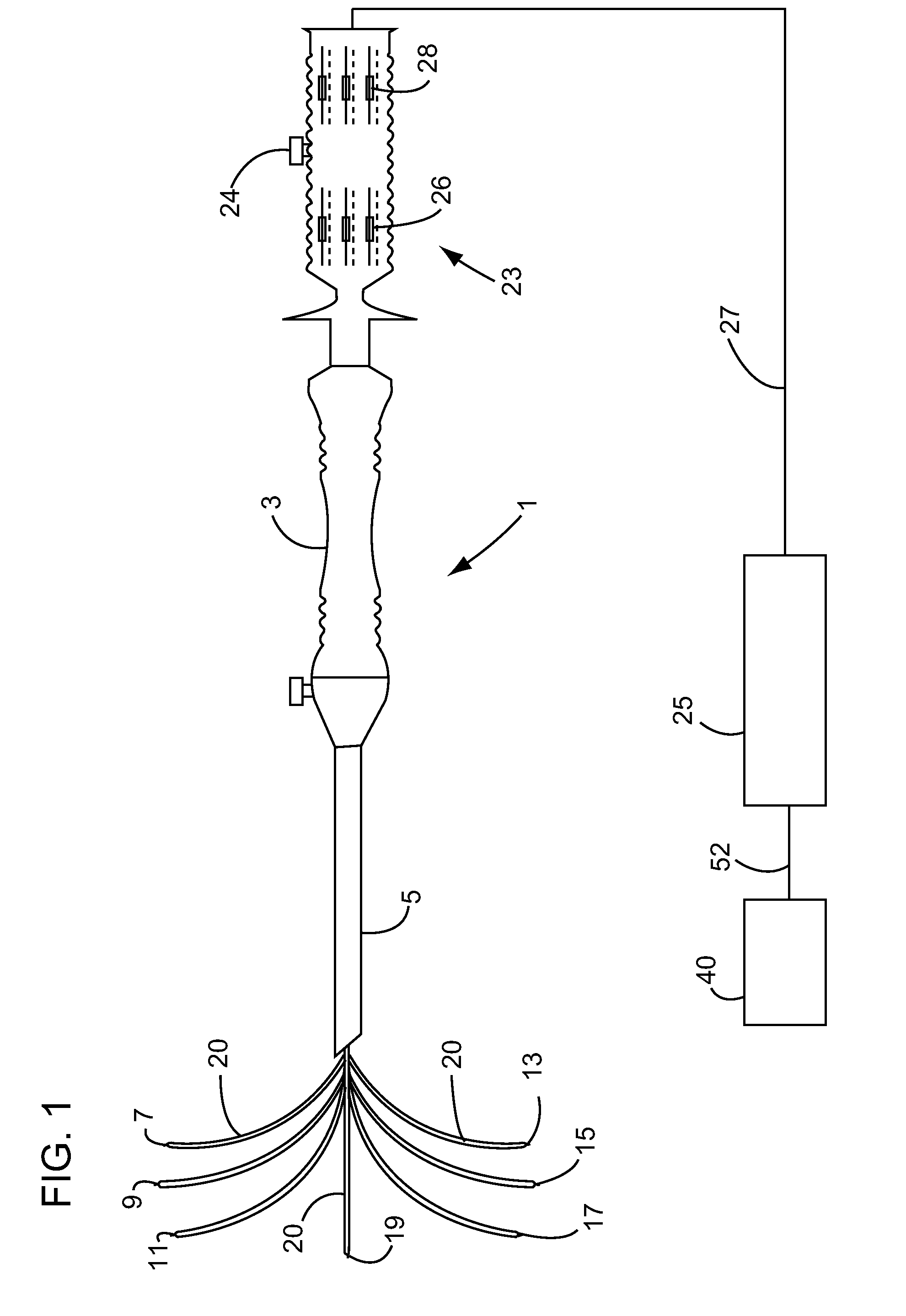
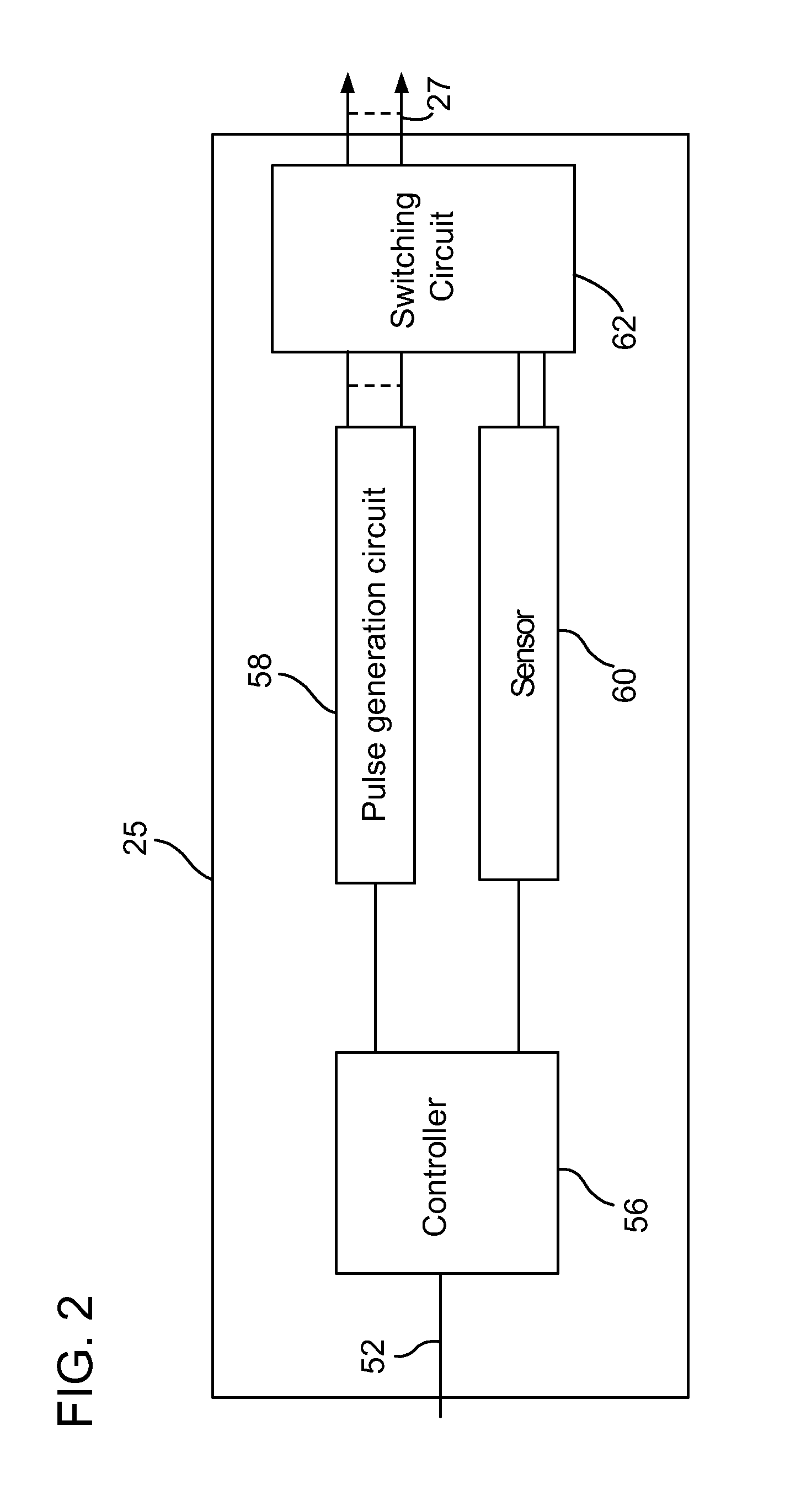
[0010]The current device and method equalizes the energy emission along the lengths of the electrodes. In one aspect, an energy delivery device for treating a patient includes a probe body and a plurality of elongate electrode elements that extend radially away from the probe body when deployed into tissue of the patient. The electrode elements are adapted to receive electrical treatment energy such as irreversible electroporation (IRE) pulses from an energy source. In another aspect of the invention, each electrode element has a longitudinally varying electrical resistance at the electrode-tissue interface along the electrode so as to provide a uniform electric field along the length of the electrode. The uniform electric field allows a more uniform ablation of tissue within a treatment zone.
[0011]In one aspect, variable resistance is accomplished by the use of a resistive element which compensates for the variation in energy emission. Specifically, the resistor / resistive element can be designed to balance energy emission by several methods including but not limited to varying the thickness of the resistor along the active electrode length, creating a pattern of holes or “defects” in the resistor element or using a resistor element with varying dielectric strength. The resistive element may also be an intrinsic component of the electrode itself such as a metallic oxide layer that may readily be grown or formed to a controlled thickness with appropriate heat processing or via anodizing. Using the device and method disclosed herein, the resistance encountered at any electrode-tissue interface point between two electrodes can be maintained at the same level regardless of the varying distance between electrodes due to the geometry of the deployed probe or non-parallel spacing during placement within the targeted tissue.

Problems solved by technology

The defects in the cell membrane lead to a disruption of homeostasis and eventually cause the cells to die.
The probe designs are similar to the RF probes and accordingly are subject to some of the same problems involving energy distribution along the electrodes.
This results in a varying electrical field strength along the electrodes which may cause incomplete treatment or system malfunction if resistance falls outside acceptable limits as determined by the hardware or software constraints.
Although the bipolar design provides efficient energy deposition in the tissue, the maximum ablation volume is limited and the resulting cylindrical shape of ablation often does not correspond with the targeted tumor shape.

Method used


Image

  • Multi-Electrode Energy Delivery Device and Method of Using the Same
  • Multi-Electrode Energy Delivery Device and Method of Using the Same
  • Multi-Electrode Energy Delivery Device and Method of Using the Same

Examples


Embodiment Construction

[0024]In the following description, and for the purposes of explanation, numerous specific details are set forth in order to provide a thorough understanding of the various aspects of the current device and method. It will be understood, however, by those skilled in the relevant arts, that the present device and method can be practiced without these specific details. In other instances, known structures and devices are shown or discussed more generally in order to avoid obscuring the present device and method. In many cases, a description of the operation is sufficient to enable one to implement the various forms of the device and method. It should be noted that there are many different and alternative configurations, devices and technologies to which the disclosed device and method can be applied. The full scope of the device and method is not limited to the examples that are described below.

[0025]For purpose of this application, the term resistance and impedance have the same mean...


PUM


Abstract

An energy delivery device for treating a patient includes a probe body and a plurality of elongate electrode elements that extend radially away from the probe body when deployed into tissue of the patient. The electrode elements are adapted to receive electrical treatment energy such as irreversible electroporation (IRE) pulses from an energy source. In one embodiment, each electrode element has a longitudinally varying electrical resistance at the electrode-tissue interface along the electrode so as to provide a uniform electric field along the length of the electrode. The uniform electric field allows a more uniform ablation of tissue within a treatment zone.

Description

CROSS REFERENCE TO RELATED APPLICATIONS[0001]This application claims priority under 35 U.S.C. 119(e) to U.S. Provisional Application No. 61 / 235,494, filed Aug. 20, 2009, which is incorporated herein by reference.FIELD OF THE INVENTION[0002]The present invention relates to medical devices. More specifically, the present invention relates to a multi-electrode energy delivery device for delivering electrical energy to treat a patient.BACKGROUND OF THE INVENTION[0003]Antenna needles can be placed within or in proximity to a tumor or other undesired tissue mass and RF energy applied between the two needles. The RF energy causes ionic agitation in the tissues surrounding the antenna and results in resistive heating of the targeted tissue as the RF energy travels from the active antennae toward the negatively charged grounding antennae. Multiple needle probes require a minimum of two insertion sites. When the probes are placed in a non-parallel relationship to each other along the active a...

Claims


Application Information

Patent Timeline
IPC IPC(8): A61B18/14
CPCA61B18/1477A61B18/148A61B2018/00083A61B2018/00196A61B2018/00613A61B2018/1475A61B2018/00875A61B2018/143A61B2018/1432A61B2018/1467A61B2018/00767
Inventor ORTIZ, MARKPEARSON, ROBERTJOE, WESLEY CHUNG
Owner ANGIODYNAMICS INC
Learn More