
PDC Bits with Mixed Cutter Blades

Active Publication Date: 2012-06-21
HALLIBURTON ENERGY SERVICES INC
View PDF4 Cites 33 Cited by
  • Summary
  • Abstract
  • Description
  • Claims
  • Application Information

AI Technical Summary

Benefits of technology

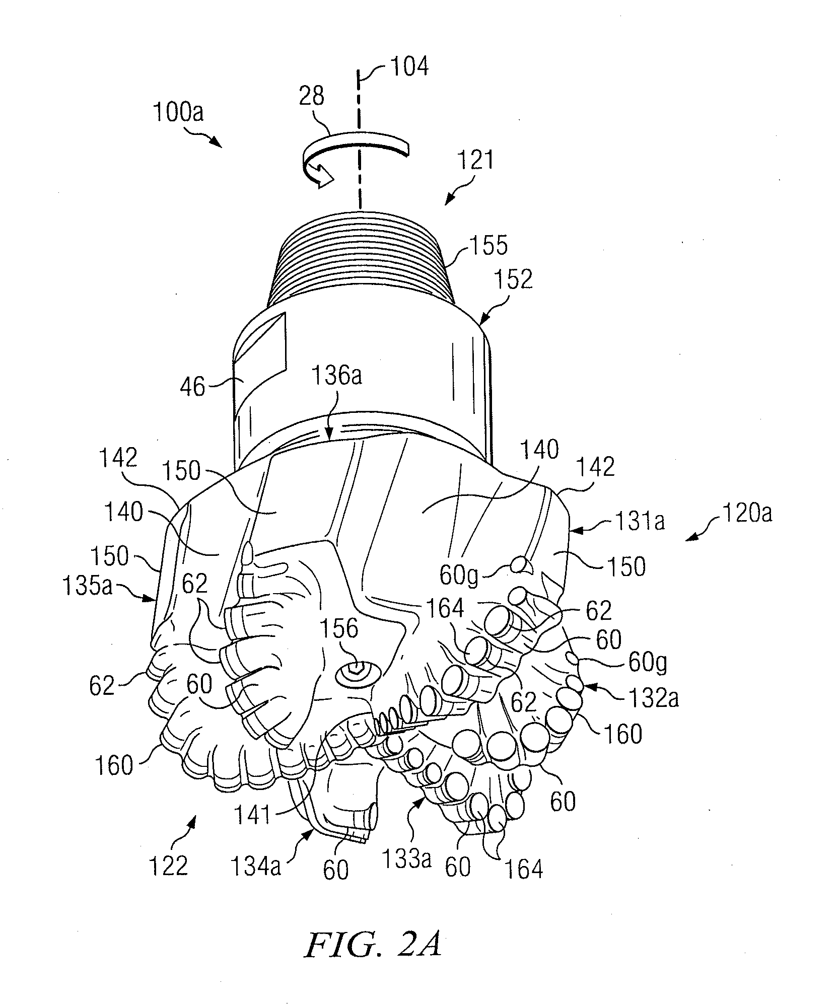
[0005]In accordance with teachings of the present disclosure, rotary drill bits and other downhole drilling tools may be designed and manufactured with various characteristics and features including, but not limited to, disposing high impact resistant and / or high wear resistant cutting elements (strong cutters which may be expensive) on blades that are subject to high impact loadings and / or on blades that remove more rock than other blades, i.e., blades subject to more loadings or high impact blades. In some embodiments, rotary drill bits and other downhole tools may be further designed by laying out cutters on blades in cutter groups comprised of cutter sets having at least a level of force balance (in some embodiments, having multilevel force balance). This may advantageously reduce or eliminate wear related damage to drilling tools and may also improve drilling performance by reducing impact and force imbalance related decreases in drilling performance. Costs of manufacture and operations may be reduced by placing low impact and / or low wear resistance cutters (weaker cutters which may be inexpensive) on blades that are not subject to high impact and / or on blades that are subject to lower loading.
[0006]Accordingly, at least two different types of cutting elements may be placed on different blades based on the function and location of blade. A first type of cutting element may comprise a high wear resistant cutting element and / or a high impact resistant cutting element that may be more expensive. In some embodiments, at least one high impact blade may have only a first type of cutting element. A second type of cutting element may comprise a low wear resistance and / or low impact resistance cutter that may be less expensive. In some embodiments, at least one low impact blade may have only a second type of cutting element.
[0007]In some embodiments, second type of cutting elements may be cheaper thereby offsetting manufacturing costs when combined with one or more expensive first type cutting elements in accordance with the present disclosure.

Problems solved by technology

However, placing different types of cutters in different bit profile zones may lead to catastrophic cutter failure and / or create “ring out” at those zones with lower abrasion resistance cutters.
Since junk slots are located between two adjacent blades, modification of blade thickness may result in modification of junk slot volume of a well drilling tool of the disclosure.

Method used


Image

  • PDC Bits with Mixed Cutter Blades
  • PDC Bits with Mixed Cutter Blades
  • PDC Bits with Mixed Cutter Blades

Examples


example 1

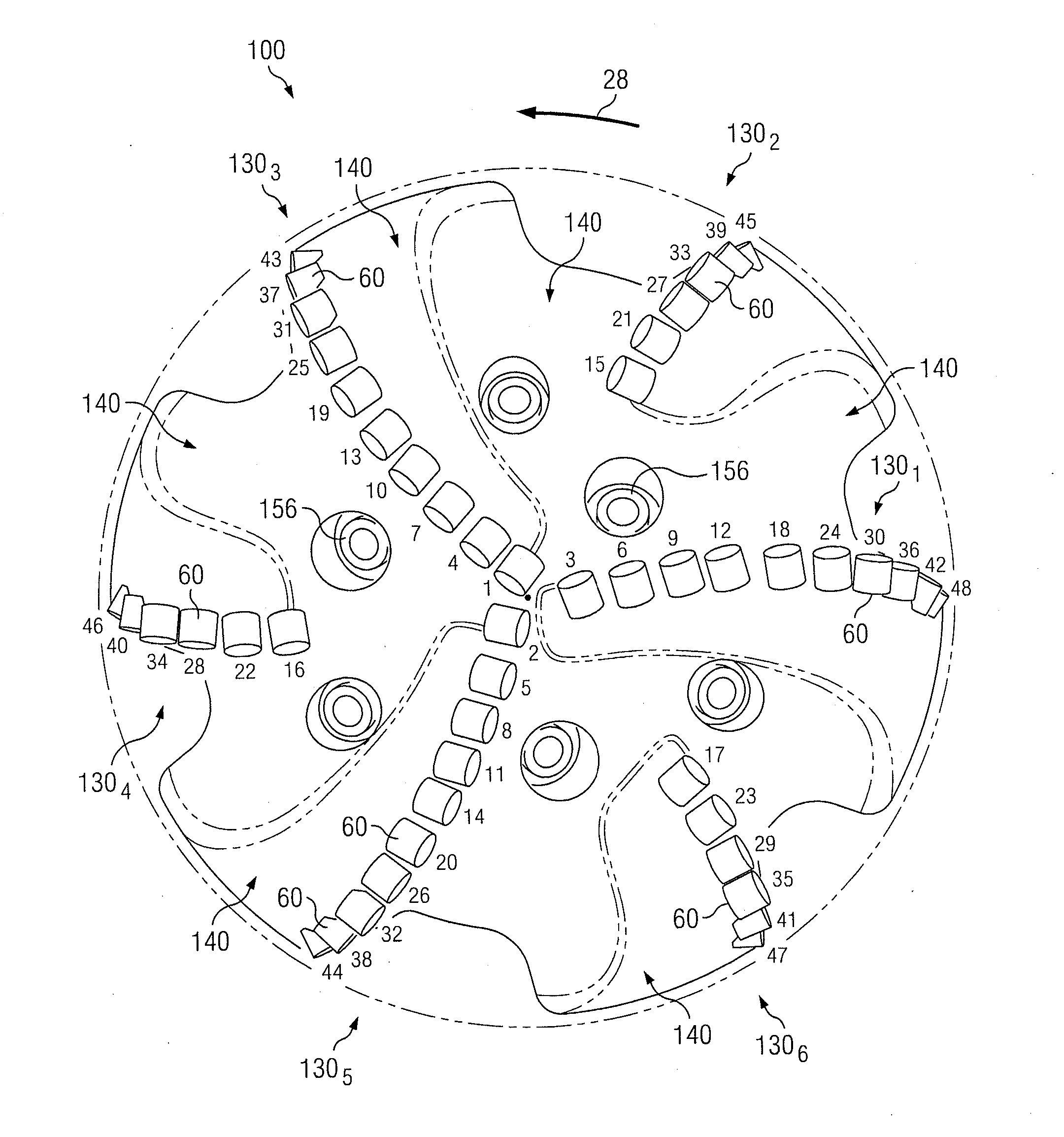
[0266]The blades of a five blade downhole drilling tool as shown in FIG. 14A may be divided into two blade groups: (1,3,5) and (2,4), where blades 131, 133 and 135 form the first blade group and blades 132 and 134 form the second blade group. The preferred match for a five blade downhole drilling tool is (1,3,5) (2,4) on Table 301 in FIG. 26A. A three cutter group may be laid out on the first blade group (1,3,5). Imbalance forces created by the three cutter group may be balanced or minimized. A pair cutter group may be laid out on the second blade group (2,4). Imbalance forces created by the pair cutter group may be balanced or minimized.

example 2

[0267]The blades of an eight blade downhole drilling tool as shown in FIGS. 15A-D may be divided into four blade groups: (1,5), (2,6), (3,7), (4,8). Four pair cutter groups may be laid out on the four blade groups. Imbalance forces created by each pair cutter group may be balanced or minimized.

[0268]Cutter Set

[0269]Following or prior to layout of one or more types of cutting elements such as 60l and 60h based on the rock volume removed by the respective blade(s) and / or on the loadings and / or impact force on cutters of the respective blade(s) on which the respective cutters are located according to the present disclosure, cutter sets may be force balanced according to the multilevel balancing embodiments. A cutter set includes at least two force balanced neighbor cutter groups. The number of cutters in one cutter set may equal the number of blades on an associated downhole drilling tool. As shown in Table 301 of FIG. 26A, a cutter set for a five blade downhole drilling tool may be [(...


PUM


Abstract

Downhole drilling tools designed and manufactured to minimize or reduce imbalance forces and wear by disposing cutting elements in cutter groups and cutter sets in a level of force balance and by placing impact and / or wear resistant cutters on blades subject to high impact forces and / or large loadings. Manufacturing costs may be reduced by placing inexpensive cutters on blades not subject to high impact forces and / or loadings. Some embodiments comprise designing downhole tools with combinations of thicker blades to receive high impact forces and / or loadings with thinner blades. Some embodiments comprise designing downhole drilling tools with optimized fluid-flow properties. Designing methods may comprise performing simulations on a designed tool, evaluating respective forces acting on cutters during simulated engagement with a downhole (uniform and transitional) and / or evaluating wear on cutters and bit, and / or CFD simulations to evaluate fluid-flow optimization on a tool. Various cutter layout procedures and algorithms are described.

Description

FIELD OF THE DISCLOSURE[0001]The present disclosure is related to downhole drilling tools including, but not limited to, rotary drill bits, core bits, and reamers and more particularly to design, manufacture and / or selection of such downhole drilling tools based at least in part on placing impact resistant cutters (e.g., high impact resistant cutters) and / or wear resistant cutters (e.g., high wear resistant cutters) on blades that are subject to high impact and / or high loadings and / or blades that remove larger rock volume while drilling and further in part on laying out cutting elements in a level of force balance to optimally balance forces associated during initial contact with the downhole end of a wellbore and during transition drilling.BACKGROUND OF THE DISCLOSURE[0002]Various types of downhole drilling tools including, but not limited to, rotary drill bits, reamers, core bits, and other downhole tools have been used to form wellbores in associated downhole formations. Examples...

Claims


Application Information

Patent Timeline
IPC IPC(8): E21B10/36G06F17/50
CPCE21B10/55E21B10/43G06F30/20G06F30/17E21B10/54
Inventor CHEN, SHILIN
Owner HALLIBURTON ENERGY SERVICES INC
Learn More