Suppressor for attachment to firearm barrel

Inactive Publication Date: 2012-06-21
LARUE MARK C
View PDF35 Cites 56 Cited by
  • Summary
  • Abstract
  • Description
  • Claims
  • Application Information

AI Technical Summary

Benefits of technology

[0014]The spaced internal tapered surfaces of the suppressor mount body and the spaced external tapered surfaces of the muzzle brake/adapter member establish spaced internal cartridge gas seals that prevent high pressure hot cartridge gas and gunpowder residue from coming into contact with and potentially fouling the thread connections of the suppressor mount body and the muzzle brake/adapter member. This feature ensures that the suppressor mechanism is easily assembled to and disassembled from a firear

Problems solved by technology

The spaced baffles within a suppressor device defines a plurality of gas expansion chambers that reduce the pressure and increase the duration of the high pressure gas discharge and consequent loud and sharp noise that eminates from the firearm barrel.
When a suppressor device is releasably attached to a firearm barrel, repeated firing of the firearm typically causes continuous fouling of the baffles, chambers and threads of the suppressor by accumulation of cartridge powder residue.
Thus, when the threads of the suppressor or the threads of a firearm barrel become fouled it may be difficult or impossible

Method used


Image

  • Suppressor for attachment to firearm barrel
  • Suppressor for attachment to firearm barrel
  • Suppressor for attachment to firearm barrel

Examples


Embodiment Construction

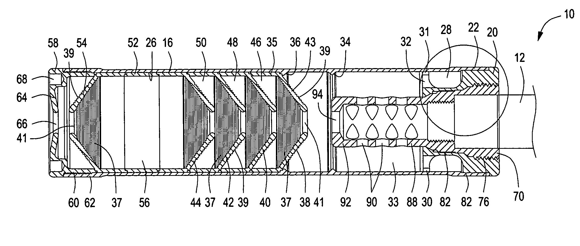
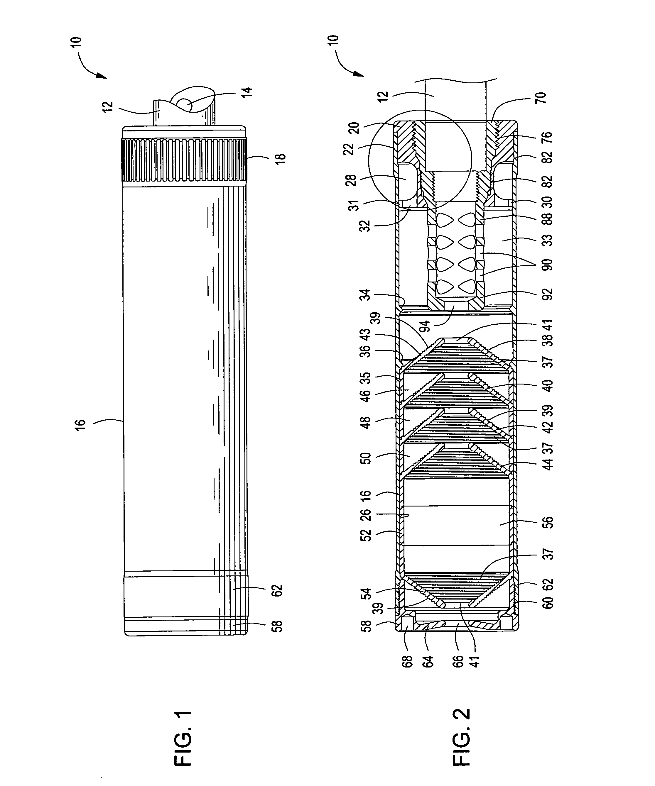
[0022]Referring now to the drawings and first to FIGS. 1 and 2, a suppressor device embodying the principles of the present invention is shown generally at 10 and is designed for releasable attachment to the muzzle end of a firearm barrel 12 having a bore 14, through which, in the case the firearm is a rifle, a bullet travels under the influence of the gas pressure that is developed when a rifle cartridge is fired in the cartridge chamber of the barrel. The outer portion of the suppressor 10 is defined by a tubular housing 16 that is preferably provided with an externally knurled section 18 that facilitates gripping of the suppressor device by a user to enable manual attachment of the suppressor device onto the barrel 12 during assembly and facilitates removal of the suppressor device from the barrel 12 as desired.

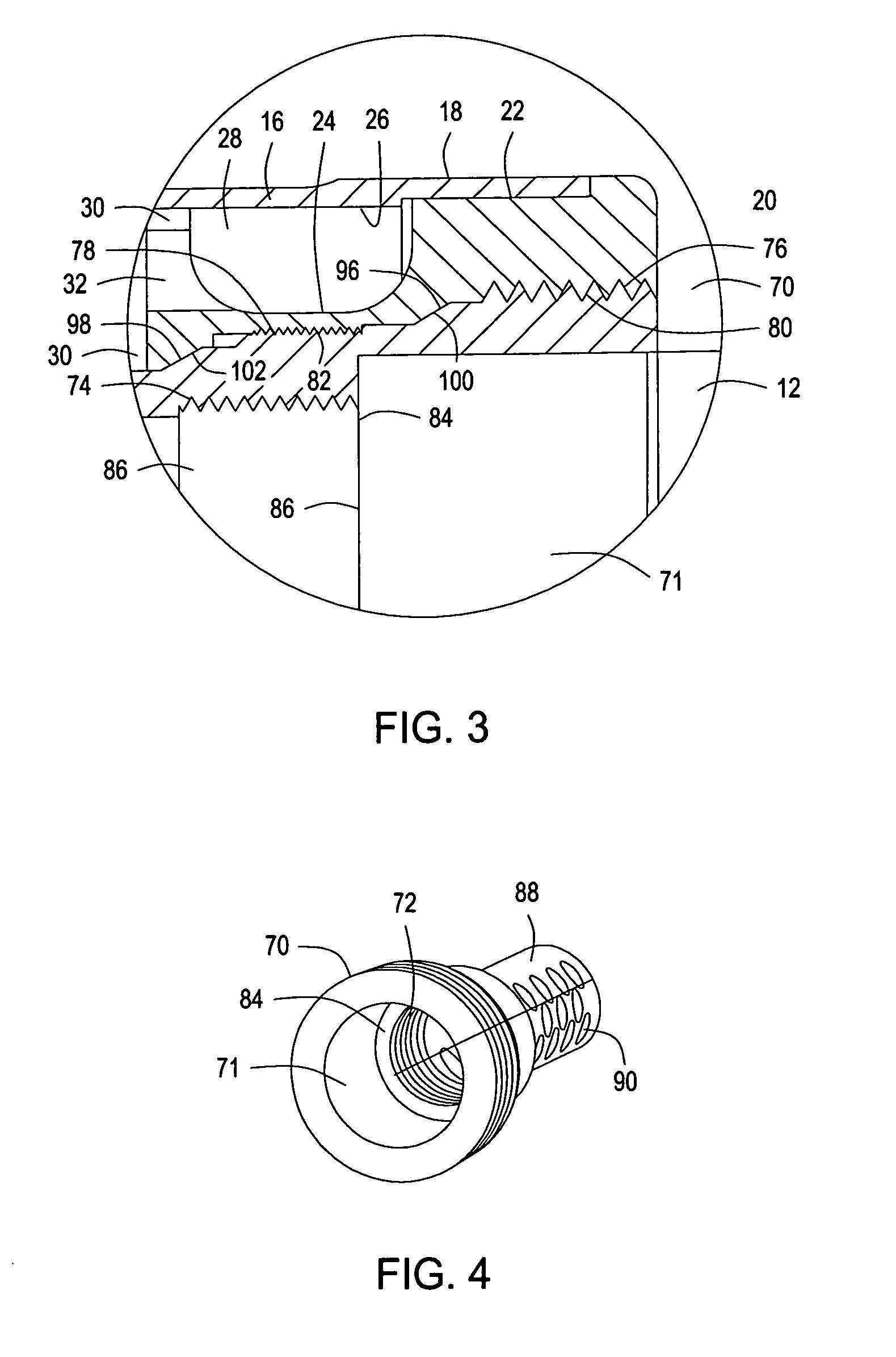
[0023]Assembly and removal of the suppressor device is typically accomplished by rotation to make-up or release threaded attachment, however, it is within the spirit and s...


PUM


Abstract

A suppressor mechanism has an elongate tubular housing containing baffles and into which is assembled a suppressor mount body having spaced thread sections and spaced tapered gas seal surfaces. An adapter/muzzle brake member defines an internally threaded section that establishes threaded connection with the reduced diameter externally threaded section of a typical firearm barrel that is prepared for attachment of a suppressor thereto. The suppressor mount body and the muzzle brake/adapter member each define spaced threaded sections that establish threaded connection and promote enhanced structural integrity. The spaced internal tapered surfaces of the suppressor mount body and the spaced external tapered surfaces of the muzzle brake/adapter member establish spaced internal cartridge gas seals that prevent high pressure hot cartridge gas and gunpowder residue from coming into contact with and potentially fouling the thread connections of the suppressor mount body and the muzzle brake/adapter member.

Description

RELATED PROVISIONAL APPLICATION[0001]Applicant hereby claims the benefit of U.S. Provisional Patent Application No. 61 / 459,936 filed on Dec. 21, 2010 by Mark C. LaRue and entitled “Suppressor For Attachment to Firearm Barrel”, which Provisional Patent Application is incorporated by reference herein for all purposes.BACKGROUND OF THE INVENTION[0002]1. Field of the Invention[0003]The present invention relates generally to firearm barrel mechanisms and assemblies and more particularly concerns a suppressor device that is assembled to or removably attached to the barrel of a rifle, handgun, machine gun or other type of firearm.[0004]2. Description of the Prior Art[0005]Suppressor devices have been developed and used for many years to minimize the noise that typically emanates from a firearm when a round of ammunition is fired. Suppressor devices are typically manufactured in the form of a tubular housing having an internally threaded section that permits the suppressor to be threadedly ...

Claims


Application Information

Patent Timeline
IPC IPC(8): F41A21/30
CPCF41A21/30F41A21/36
Inventor LARUE, MARK C.
Owner LARUE MARK C
Why Eureka
Try Eureka