

Organic electroluminescence device
- Summary
- Abstract
- Description
- Claims
- Application Information
AI Technical Summary
Benefits of technology
Problems solved by technology
Method used
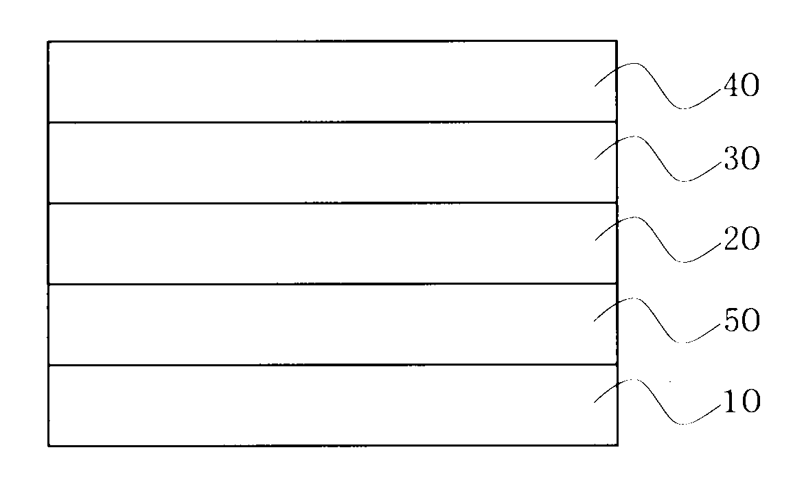
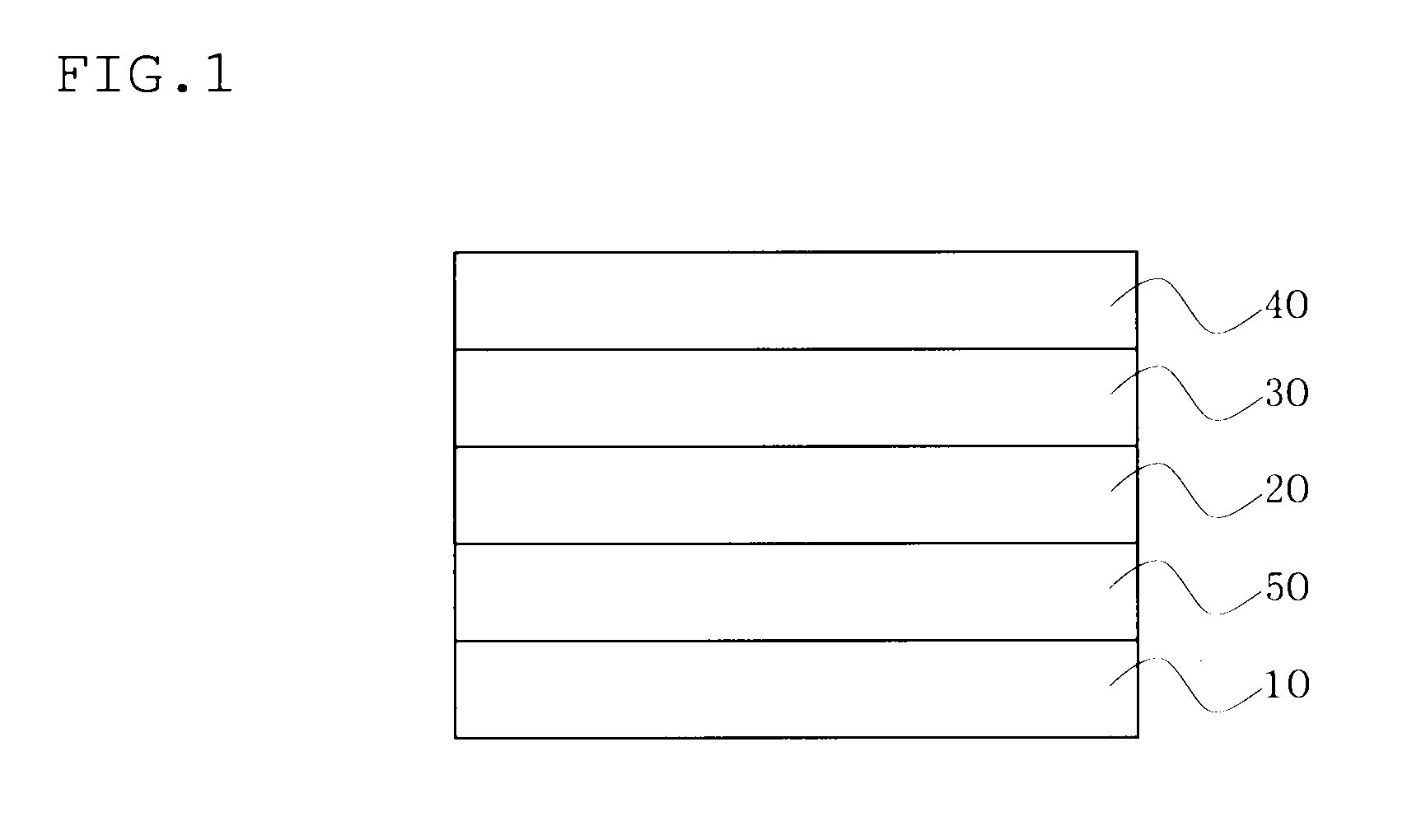
Image

Examples
first embodiment
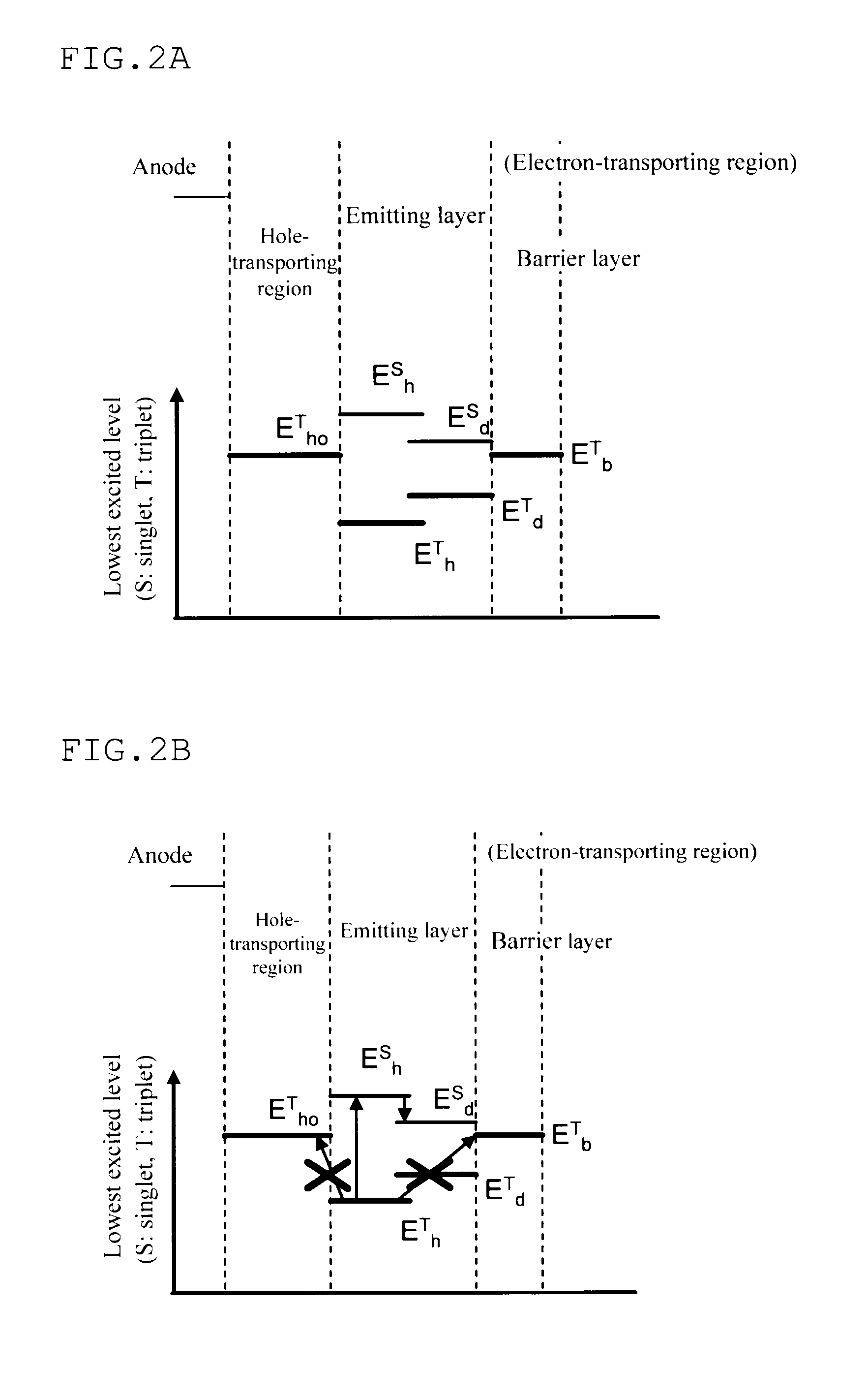
[0042]The invention utilizes the TTF phenomenon. First, an explanation is made of the TTF phenomenon.
[0043]Holes and electrons injected from an anode and a cathode are recombined with in an emitting layer to generate excitons. As for the spin state, as is conventionally known, singlet excitons account for 25% and triplet excitons account for 75%. In a conventionally known fluorescent device, light is emitted when singlet excitons of 25% are relaxed to the ground state. The remaining triplet excitons of 75% are returned to the ground state without emitting light through a thermal deactivation process. Accordingly, the theoretical limit value of the internal quantum efficiency of a conventional fluorescent device is believed to be 25%.
[0044]The behavior of triplet excitons generated within an organic substance has been theoretically examined. According to S. M. Bachilo et al. (J. Phys. Chem. A, 104, 7711 (2000)), assuming that high-order excitons such as quintet excitons are quickly r...
second embodiment
[0111]The device according to the invention may include at least two emitting layers (units including the emitting layer) (i.e., tandem device configuration). A carrier-generating layer (CGL) is provided between two emitting layers. The electron-transporting region may be provided corresponding to each unit. At least one of the emitting layers is a fluorescent emitting layer, and the unit including the fluorescent emitting layer satisfies the above requirements. Specific examples of the configuration are shown below. Each emitting layer may be formed by stacking a plurality of emitting layers.
[0112]Anode / fluorescent emitting layer / carrier-generating layer / fluorescent emitting layer / barrier layer / cathode
[0113]Anode / fluorescent emitting layer / barrier layer / carrier-generating layer / fluorescent emitting layer / cathode
[0114]Anode / fluorescent emitting layer / barrier layer / carrier-generating layer / fluorescent emitting layer / barrier layer / cathode
[0115]Anode / phosphorescent emitting layer / carri...
third embodiment
[0120]An organic EL device according to a third embodiment of the invention includes an anode, a plurality of emitting layers, an electron-transporting region, and a cathode that are stacked in this order, and includes a carrier barrier layer between two emitting layers among the plurality of emitting layers, the emitting layer that is adjacent to the electron-transporting region being a fluorescent emitting layer that satisfies the above requirements.
[0121]Examples of a preferable configuration of the organic EL device according to the third embodiment include a configuration in which an anode, a first emitting layer, a carrier barrier layer, a second emitting layer, and a cathode are stacked in this order (see Japanese Patent No. 4134280, US2007 / 0273270A1, and WO2008 / 023623A1), wherein an electron-transporting region that includes a barrier layer that prevents diffusion of triplet excitons is provided between the second emitting layer and the cathode. The term “carrier barrier lay...
PUM
 Abstract
Description
Claims
Application Information