Microelectromechanical transducer and corresponding assembly process

Active Publication Date: 2012-06-21
STMICROELECTRONICS SRL +1
View PDF1 Cites 58 Cited by
  • Summary
  • Abstract
  • Description
  • Claims
  • Application Information

AI Technical Summary

Benefits of technology

[0019]The present disclosure is directed to an appropriate assembly of a MEMS acoustic transducer and of a corresponding package, which will enable solutio

Problems solved by technology

As a result of the forces of inertia of the air mass leaving the front chamber, the increase of pressure inside the same chamber is over-compensated, causing a pressure drop, and the negative pressure that is created in the front chamber attracts new air therein.
In the design stage, it has also to be considered that the presence of acoustic access ports, directly communicating with the external environment, designed to enable entry of the acoustic pressure waves towards the membrane 4 of the micromechanical sensing structure, involves the further requirement of pre-arranging appropriate shields for the incident light, which could jeopardize proper operation of the micromechanical sensing structure and of the reading electronics.
Several constraints are thus imposed on the assembly of a MEMS acoustic transducer (and of the corresponding package), which render design thereof particularly problematical, especially where compact dimensions and hi

Method used


Image

  • Microelectromechanical transducer and corresponding assembly process
  • Microelectromechanical transducer and corresponding assembly process
  • Microelectromechanical transducer and corresponding assembly process

Examples


Example

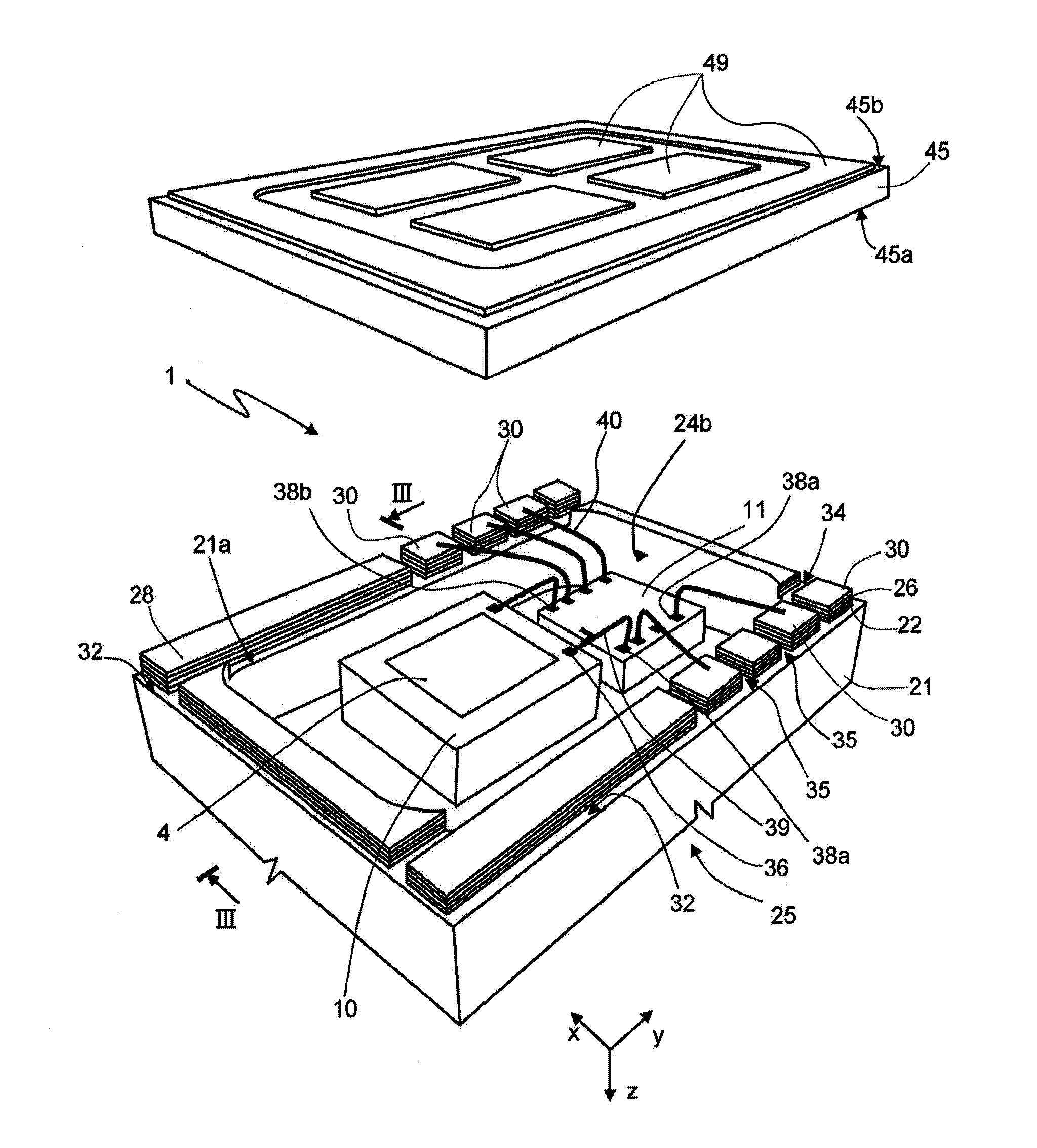
[0036]As will be discussed in detail in what follows, one aspect of the present disclosure envisages providing a specific cap structure for the package of a MEMS acoustic transducer, of a composite type, constituted by the assembly of two layers made of a same plastic material, obtained with standard semiconductor techniques (such as standard techniques for obtaining BGA, LGA substrates, or the like). In addition, one or both of the dice of the MEMS acoustic transducer (integrating the micromechanical sensing structure and, respectively, the corresponding ASIC), and / or further electrical / electronic components, are directly coupled to the cap structure, instead of being coupled to a substrate to which the same cap structure is bonded for providing the package of the MEMS acoustic transducer and its connection to an external printed circuit board.

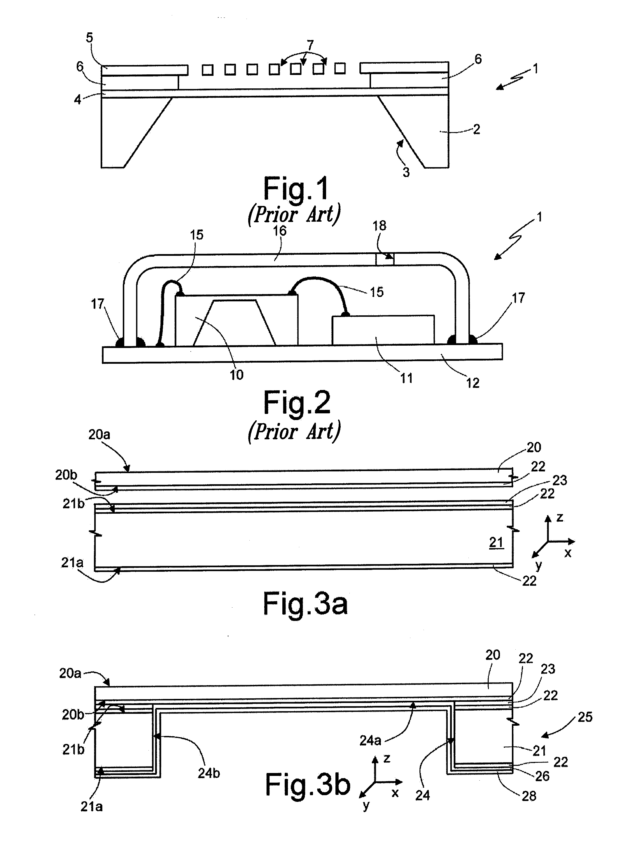
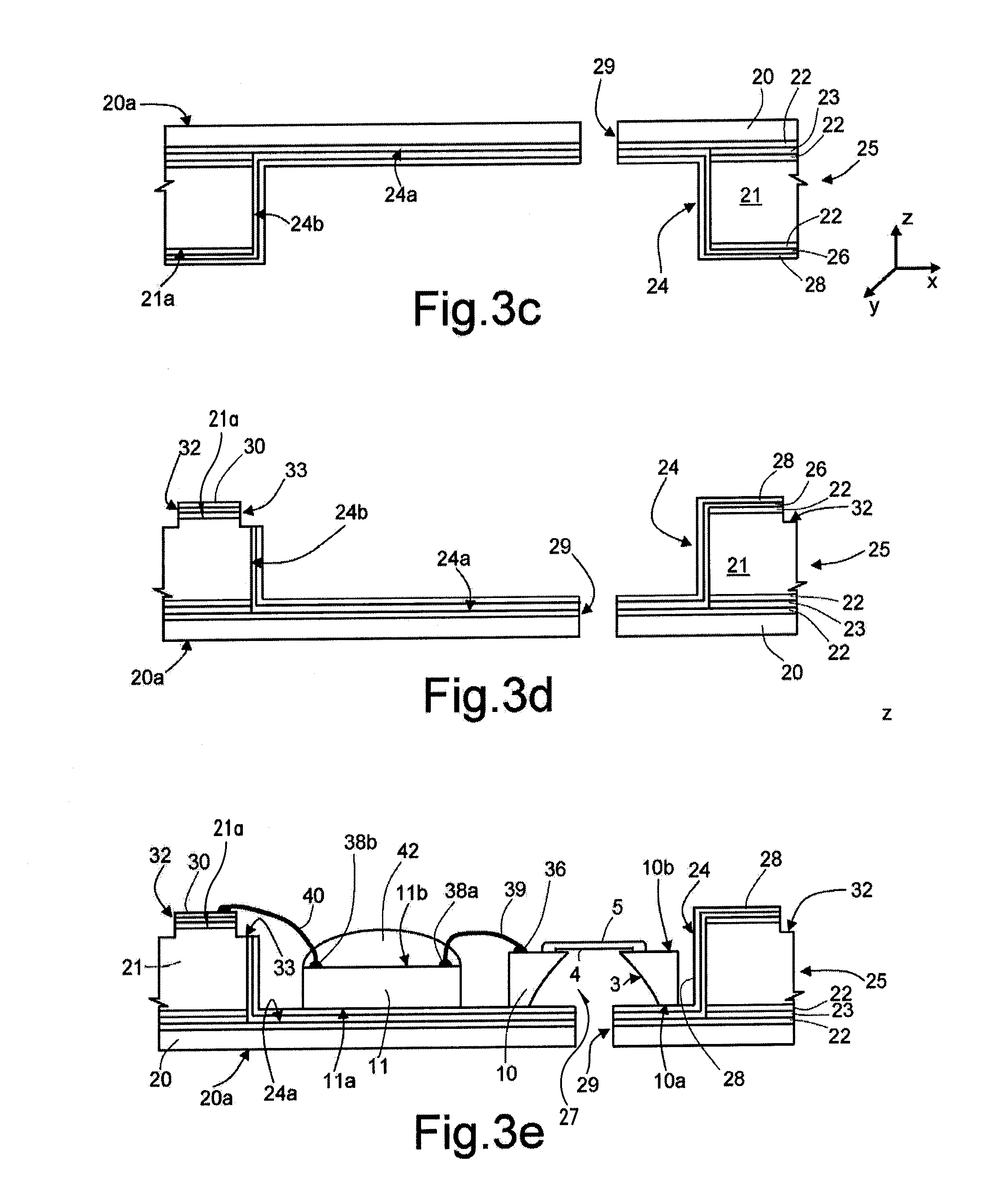
[0037]In detail, and with reference firstly to FIG. 3a, a process of assembly of a MEMS acoustic transducer initially envisages providing a ...


PUM

PropertyMeasurementUnit
Pressureaaaaaaaaaa
Electrical conductoraaaaaaaaaa
Areaaaaaaaaaaa

Abstract

A MEMS transducer has a micromechanical sensing structure and a package. The package is provided with a substrate, carrying first electrical-connection elements, and with a lid, coupled to the substrate to define an internal cavity, in which the micromechanical sensing structure is housed. The lid is formed by: a cap layer having a first surface and a second surface, set opposite to one another, the first surface defining an external face of the package and the second surface facing the substrate inside the package; and a wall structure, set between the cap layer and the substrate, and having a coupling face coupled to the substrate. At least a first electrical component is coupled to the second surface of the cap layer, inside the package, and the coupling face of the wall structure carries second electrical-connection elements, electrically connected to the first electrical component and to the first electrical-connection elements.

Description

BACKGROUND[0001]1. Technical Field[0002]The present disclosure relates to a transducer of a MEMS (Micro-Electro-Mechanical System) type, in particular a capacitive microphone, to which the ensuing treatment will make explicit reference, without this implying any loss of generality, and to a corresponding assembly process.[0003]2. Description of the Related Art[0004]As it is usual in this technical field, the term “package” will be used herein to designate, as a whole, the casing, or covering structure, which surrounds, completely or partially, the die or dice of semiconductor material constituting the acoustic transducer, enabling electrical connection thereof to the outside (in particular, connection to a printed circuit of a corresponding electronic device).[0005]As is known, an acoustic transducer, for example a MEMS microphone of a capacitive type, generally comprises a micromechanical sensing structure, designed to transduce acoustic pressure waves into an electrical quantity (...

Claims


Application Information

Patent Timeline
IPC IPC(8): H02N1/00H01R43/00
CPCB81B2201/0257H01L2924/3025B81B2207/07B81B2207/093B81C1/0023B81C2203/019B81C2203/035B81C2203/0785B81C2203/0792H04R19/005H01L2224/48091H01L2224/48137Y10T29/49117H01L2924/1461H01L2924/10253H01L2224/8592B81B2207/012H01L2924/00014H01L2924/00H01L2224/05554H01L2924/16151
Inventor FORMOSA, KEVINAZZOPARDI, MARK ANTHONYCORTESE, MARIO FRANCESCOSHAW, MARKGRITTI, ALEXMAGGI, LUCADAVID, FILIPPO
Owner STMICROELECTRONICS SRL
Why Eureka
Try Eureka