

Optical packet switching system and optical packet transmitter device
a technology of optical packet transmitter and optical packet, which is applied in the direction of transmission monitoring, multiplex communication, electromagnetic transmission, etc., can solve the problems of insufficient time and waste of bandwidth, and achieve the effect of reducing the ratio of discarded optical packet signals
- Summary
- Abstract
- Description
- Claims
- Application Information
AI Technical Summary
Benefits of technology
Problems solved by technology
Method used
Image

Examples
first embodiment
[0024]FIG. 3 shows an optical packet switching system according to the first embodiment of the present invention. As shown in FIG. 3, an optical packet switching system 100 comprises a 2-input×2-output optical packet switching device 10 and an optical packet transmitter device 12.
[0025]A description will first be given of the optical packet switching device 10 The optical packet switching device 10 is provided with the function of switching the path of, i.e., routing, an input optical packet signal and outputting the signal accordingly. As shown in FIG. 3, the optical packet switching device 10 comprises an optical switch 14, an optical switch control unit 16, a first optical coupler 18, a second optical coupler 20, a first optical delay line 22, and a second optical delay line 24.
[0026]The optical packet signal input to the optical packet switching device 10 via an optical transmission path 17 is input to the first optical coupler 18. The first optical coupler 18 causes the optical...
second embodiment
[0043]FIG. 5 shows the operation of the optical packet switching device in the optical packet switching system according to a second embodiment of the present invention. The components of the optical packet switching system according to the second embodiment are basically identical to the components of the optical packet switching system shown in FIG. 3 and so are denoted by like symbols. A detailed description is omitted.
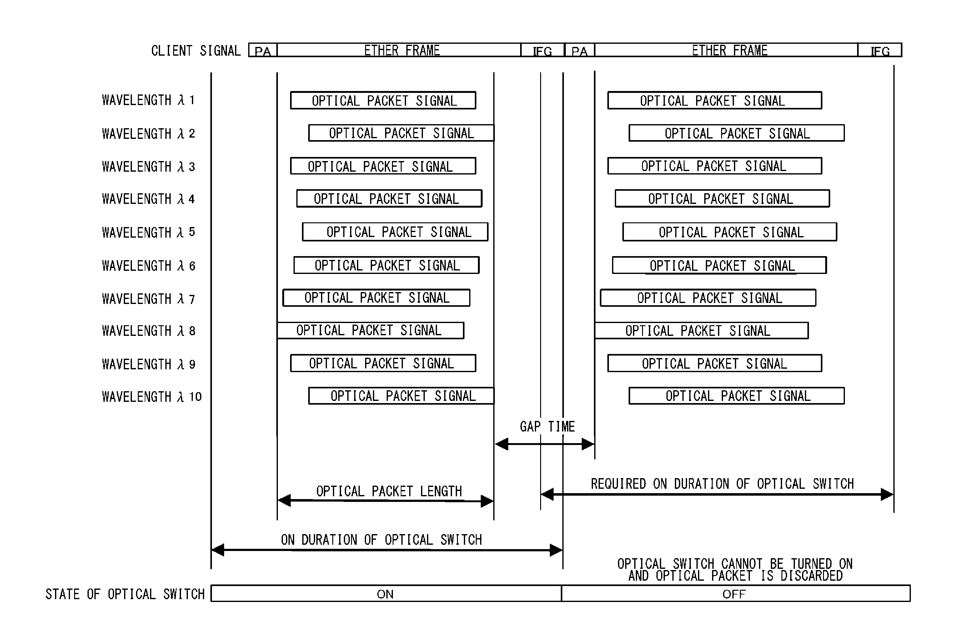
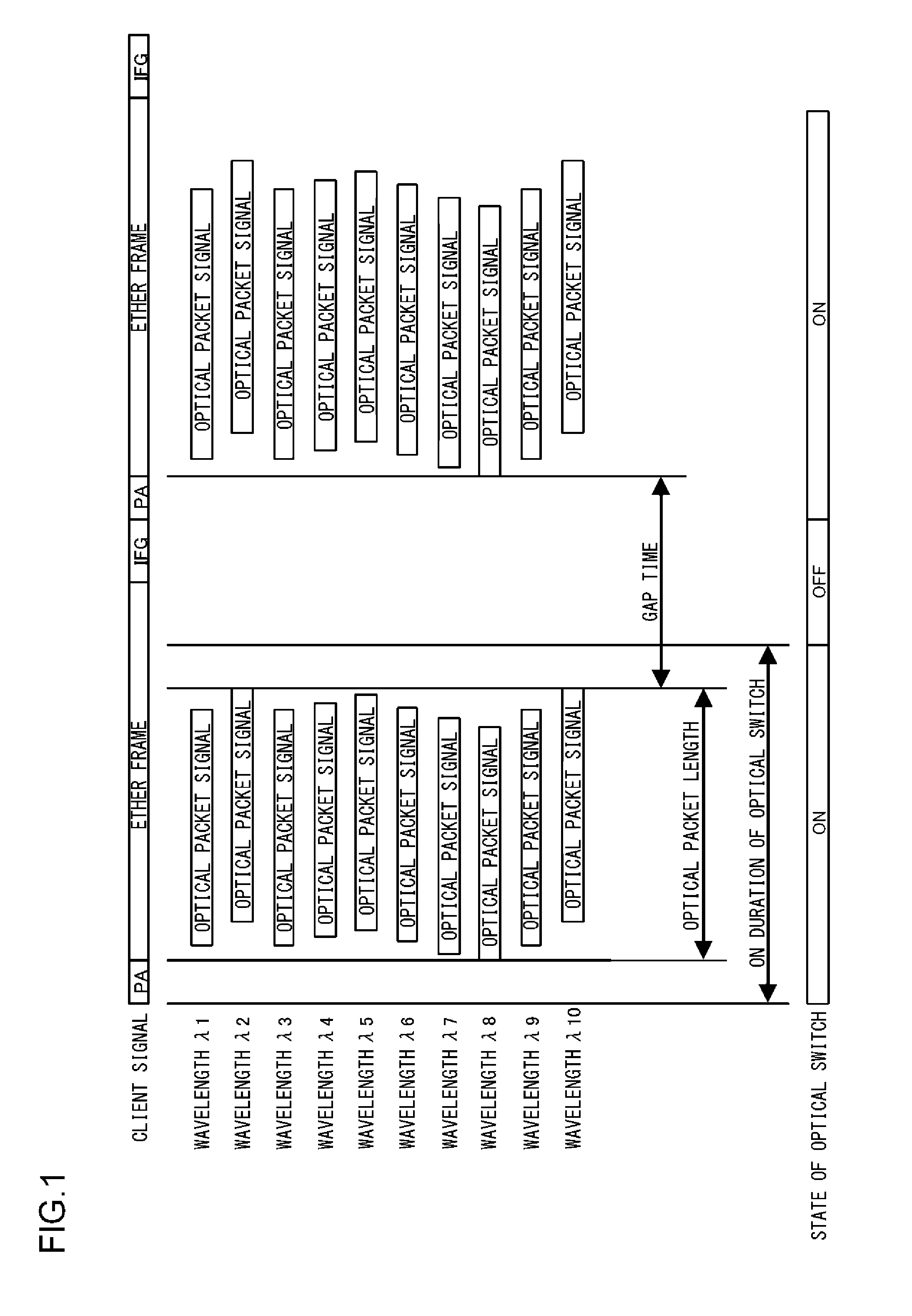
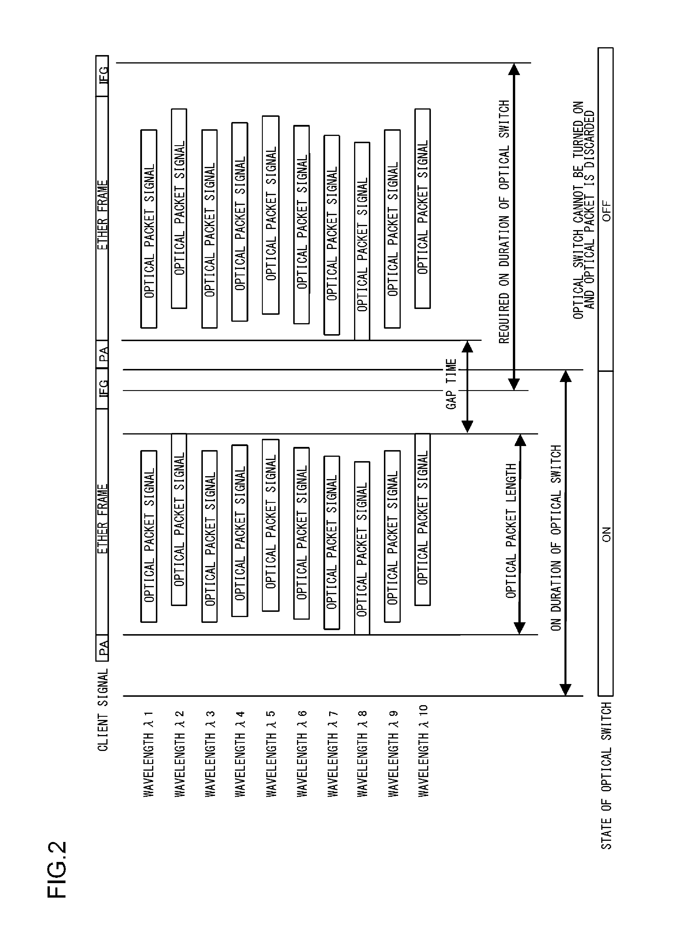
[0044]The operation of the delay processing unit 52 of the optical packet transmitter device 12 in the optical packet switching system 100 according to the second embodiment differs from that of the first embodiment. In the first embodiment, the delay processing unit 52 adjusts the timing of outputting an optical packet signal so that the gap time between packet signals has a fixed value. In the second embodiment, the delay processing unit 52 controls the timing of outputting a packet signal and adjusts the gap time in accordance with the length of a client signal ...
third embodiment
[0046]FIG. 6 shows an optical packet switching system according to a third embodiment of the present invention. Those components of the optical packet switching system 100 shown in FIG. 5 that are identical or corresponding to the components of the optical packet switching system shown in FIG. 3 are denoted by like symbols and a detailed description is omitted.
[0047]In optical packet switching in the optical packet switching device 10, optical packet signals from a specific input port could be more likely to be discarded than those from the other ports. The third embodiment addresses this by feeding back information on the ratio of discarded optical packets to the optical packet transmitter device 12 and adjusting the gap time so that the ratio of discarded packets is reduced.
[0048]The optical switch control unit 16 of the optical packet switching device 10 in the optical packet switching system 100 according to the third embodiment further comprises a discarded ratio calculation un...
PUM
 Abstract
Description
Claims
Application Information