Integrated pump, coolant flow control and heat exchange device

a technology of integrated pumps and heat exchange devices, which is applied in the direction of mechanical equipment, machines/engines, transportation and packaging, etc., can solve the problems of not fully utilizing the maximum cooling potential of transmission oil cooling, the cooling valve does not provide a more rapid increase in the temperature of the transmission oil circuit, and the oil in the cooler can get so cold and thick, so as to improve the fuel economy and heat exchange management. , the effect of improving the efficiency of cooling and heating

Active Publication Date: 2012-07-05
HYUNDAI MOTOR CO LTD +2
View PDF20 Cites 19 Cited by
  • Summary
  • Abstract
  • Description
  • Claims
  • Application Information

AI Technical Summary

Benefits of technology

[0014]In its broadest aspects, the present invention features an integrated coolant delivery, flow control and heat exchange device which pumps or delivers coolant to an engine while controlling multiple flow modes and coolant paths to branch out (or converge) from (or to) a coolant flow valve which in turn controls all paths of coolant flow through a heat exchange mixing box. Such an integrated coolant delivery, flow control and heat exchange device should improve both fuel economy and management of heat exchange between components of a vehicle using such a device. More particularly, such improvement is expected when using the device of the present invention for a number of reasons including, for example, (a) optimizing flow control speed to actual needs rather than engine speed; (b) keeping the pump off on a cold start; (c) allowing interior heating with engine coolant rather than electric auxiliary heat on shutdown (start-stop for hybrids); (d) allowing faster oil warm-up (both engine & transmission); (e) allowing faster cold engine warm-up (optimize coolant flow); (f) reducing water pump load (minimize high flow pressure drop); (g) improving temperature control (minimize coolant and engine oil temperature variation within engine and increase cold weather transmission oil operating temperatures (“Oil heating mode in cold weather conditions”); and / or (h) allowing for engine coolant operating temperature calibration for optimum efficiency at any operating condition through the engine control module or other control device (e.g., digital signal processor) as is known to those skilled in the art and suitable for the intended purpose.
[0027]The valve body part includes a first inlet for receiving coolant coming from the engine, a second inlet for receiving coolant coming from the radiator, and a third inlet for receiving coolant coming from the unit heater. The valve body part further includes an outlet and the heat exchange part further includes an inlet. The outlet of the valve body part is connected (e.g., fluidly coupled) to the inlet of the heat exchange part so that all of the coolant inside the valve body part can be delivered to the heat exchange part to warm up and cool down the vehicle fluid inside the heat exchanger by heat exchange there between.

Problems solved by technology

The coolant control valve, however, does not provide a more rapid increase in the temperature of the transmission oil circuit because of the positional limitation of a transmission oil cooler.
Accordingly, as the coolant flows through the multiple coolant circuits, the transmission oil cooler is not fully utilizing the maximum cooling potential available for transmission oil cooling.
In case of the air to oil transmission oil cooler, if there is no temperature bypass valve in the flow circuit, the oil in the cooler can get so cold and thick that the oil cooler may freeze and may not ever allow oil to pass through the cooler.
In some cases, this may cause the transmission to be overheated and be damaged due to no oil flow through the transmission oil cooler.
An additional parasitic loss to the engine fuel economy performance is the engine driven mechanical water pump.

Method used


Image

  • Integrated pump, coolant flow control and heat exchange device
  • Integrated pump, coolant flow control and heat exchange device
  • Integrated pump, coolant flow control and heat exchange device

Examples


Embodiment Construction

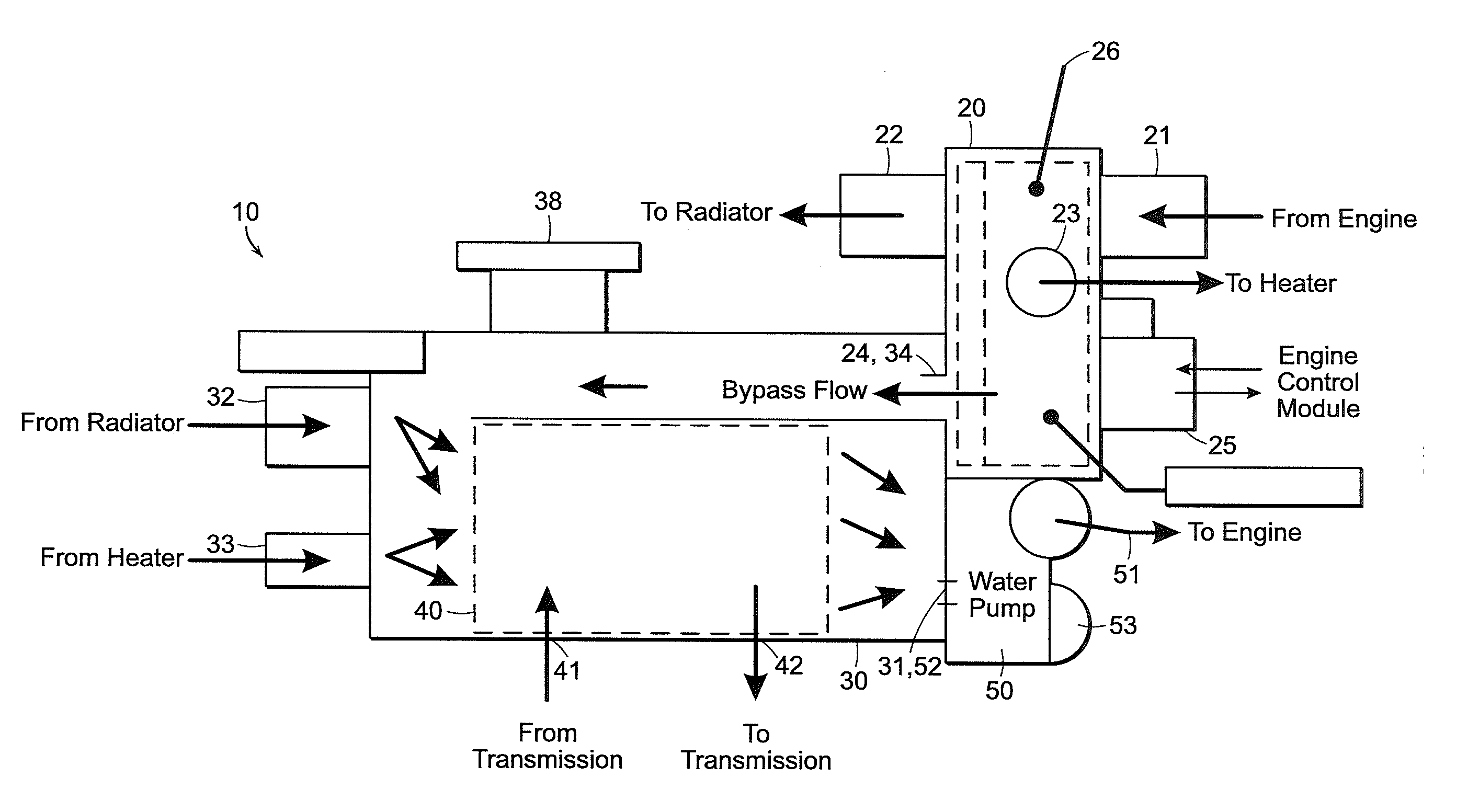
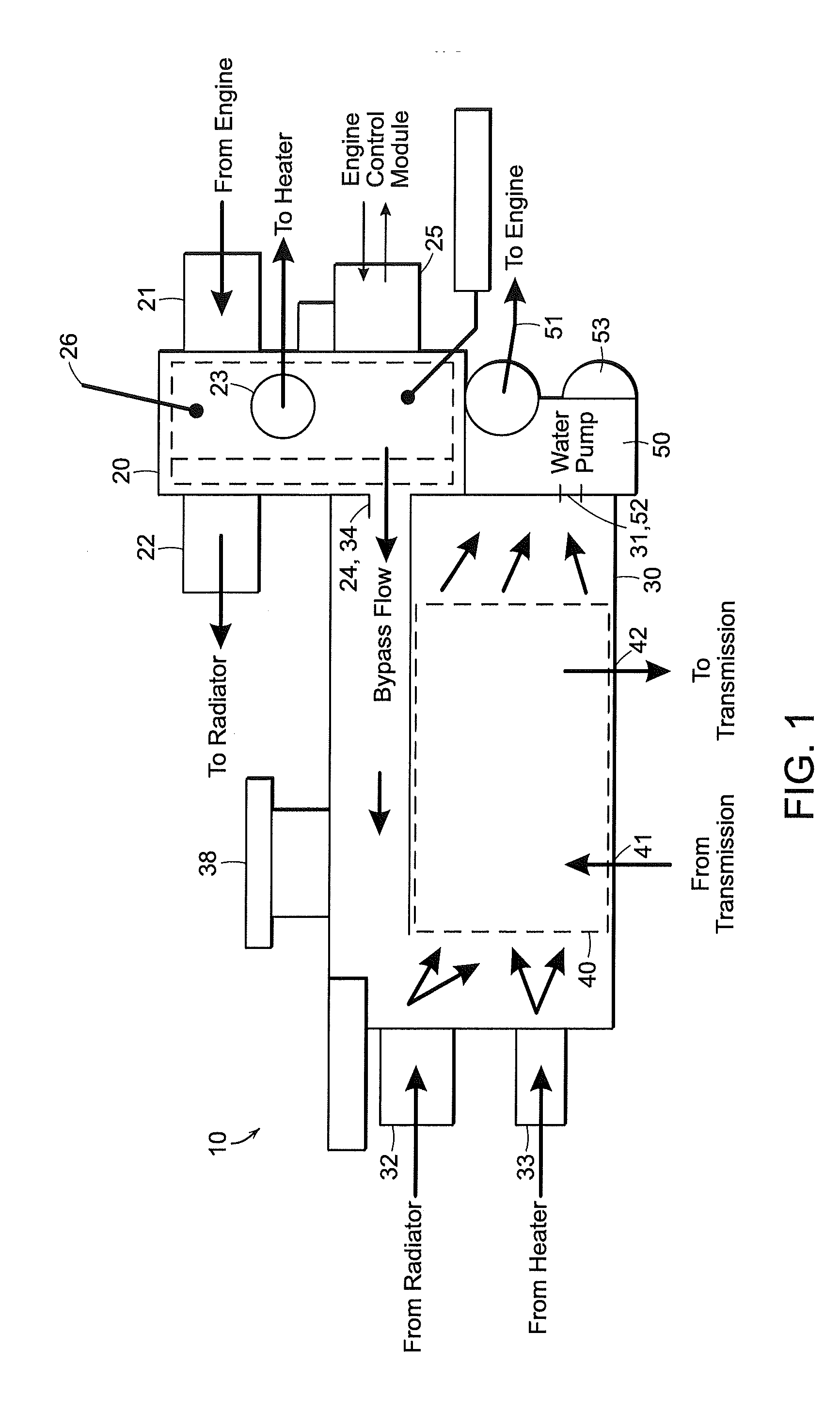
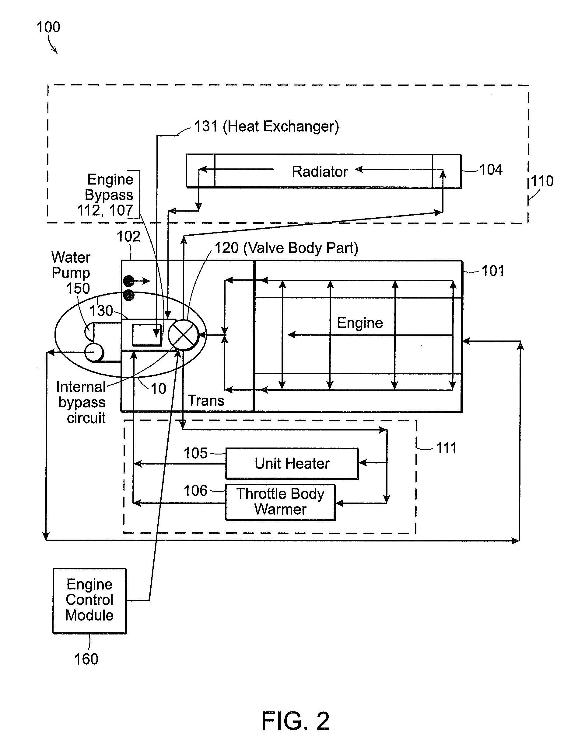
[0043]As discussed above, we now provide an integrated pump, flow control and heat exchange device and an integrated coolant delivery, flow control and heat exchange system (e.g., coolant flow system) embodying such an integrated pump, flow control and heat exchange device. Such systems or devices in their broadest aspects, pump or deliver coolant to an engine (e.g., internal combustion engine and / or electric motor or electric drive motor) while controlling multiple flow modes and coolant paths to, branch out (or converge) from (or to) a coolant flow valve which in turn controls all paths of coolant flow through a heat exchange mixing box. In more particular aspects, such systems and devices of the present invention, comprises an integrated pump for delivering engine coolant to the engine, coolant flow control and heat exchange device for a vehicle.

[0044]Systems and devices of the invention can provide notable advantages over prior systems, including for example, eliminating the nee...


PUM


Abstract

A coolant flow control management system includes an integrated pump coolant flow control and heat exchange device for delivering engine coolant to and from the engine. According to the system, coolant flows from the engine and is delivered back to the engine after passing through various coolant branches while flow is regulated by a control valve part of said device, then passes through a heat exchanger part before being returned to the engine by a pump part. Systems of the invention are particularly useful with all-electric and hybrid vehicles.

Description

[0001]This application is a continuation-in-part of copending U.S. application Ser. No. 12 / 982,846, filed Dec. 30, 2010, the teachings of which are incorporated herein by reference.BACKGROUND[0002](a) Technical Field[0003]The present invention generally relates to systems and devices for delivering coolant to an engine of a vehicle, such as electric-powered vehicles and hybrid vehicles (e.g., vehicles powered by an electric motor(s) and / or an internal combustion engine). More particularly, the present invention relates to an integrated pump, coolant flow control and heat exchange device and systems embodying same and yet more particularly, to such an integrated pump, flow control and heat exchange device having the ability to simultaneously control flow paths and flow volume.[0004](b) Background Art[0005]Generally, a vehicle includes an engine, a transmission, a unit heater, a radiator, a pump for delivering coolant to the engine, and an engine control module. A typical cooling syst...

Claims


Application Information

Patent Timeline
Patent Type & Authority Applications(United States)
IPC IPC(8): B60H1/00
CPCB60L11/14F01P5/10F01P11/08F01P2060/08Y02T10/70F02M15/02F02M25/0795Y02T10/7077F01P2060/18F02M26/73
Inventor MYERS, JOHN W.BOURCIER, MARK A.
Owner HYUNDAI MOTOR CO LTD
Why Eureka
Try Eureka