Optical transmitter, optical transmission method, and wavelength-selective variable delayer
a wavelength-selective variable delayer and optical transmission technology, applied in the field of optical transmission methods, can solve the problems of affecting the reception quality of phase modulation optical signals, severe waveform degradation, and degrade transmission performance, so as to reduce transmission quality degradation, enhance system performance, and improve network flexibility. the effect of design and management flexibility
- Summary
- Abstract
- Description
- Claims
- Application Information
AI Technical Summary
Benefits of technology
Problems solved by technology
Method used
Image
Examples
first embodiment
[A] First Embodiment
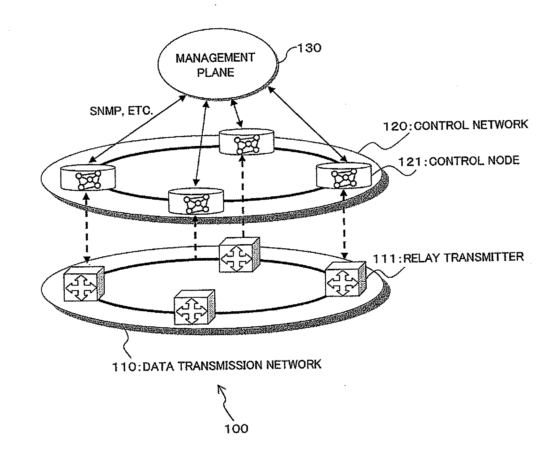
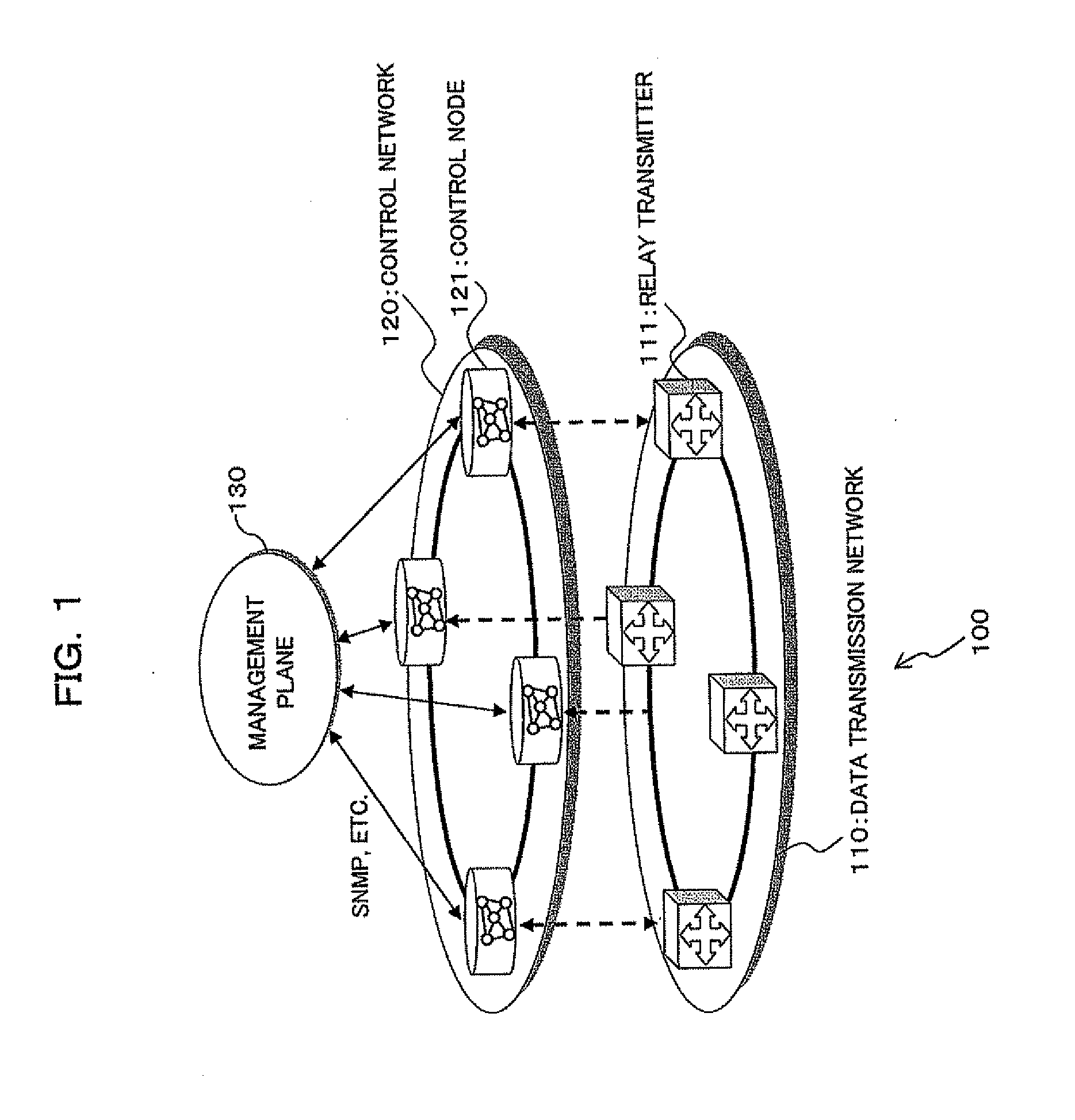
[0093]Referring to FIG. 1, there is shown a network system to which an optical transmitter according to a first embodiment of the present invention is applied. The network system 100 shown in the figure is constituted by a data transmission network 110, a control network 120 which controls the data transmission network 110, and a management plane 130 which manages the control network 120. The data transmission network 110 includes a plurality of optical transmitters 111, which are interconnected. The control network 120 includes a plurality of control nodes 121, which are connected with one another and disposed so as to correspond to the optical transmitters 111 forming the data transmission network 110.
[0094]With the above configuration, the control nodes 121 forming the control network 120 extract information from the optical transmitters (relay transmitters) 111 of the data transmission network 110 (which are target objects in the data transmission network 110...
second embodiment
[B] Second Embodiment
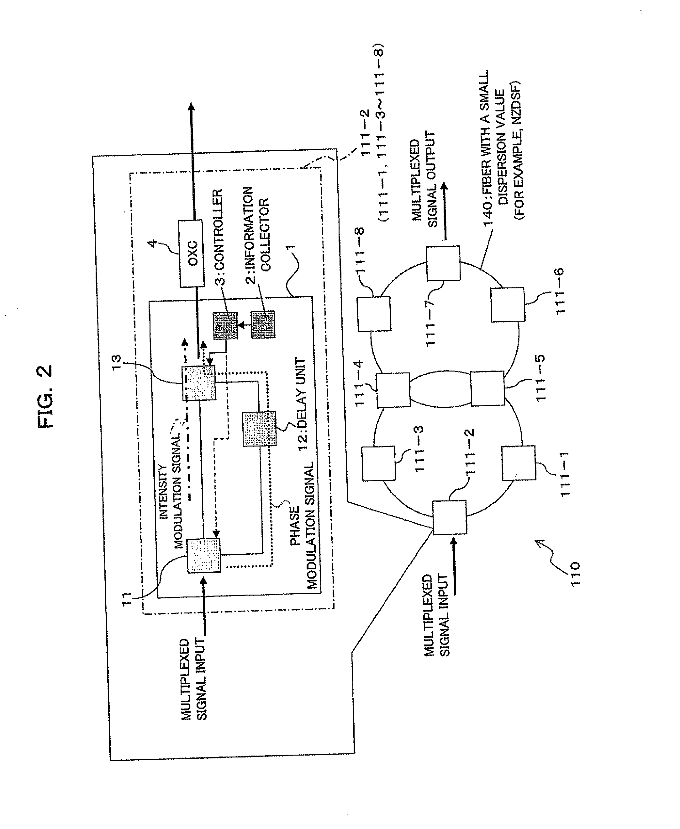
[0164]Referring to FIG. 20, there is shown an optical transmitter 111A according to a second embodiment of the present invention. The optical transmitter 111A differs from the optical transmitter 111 (see FIG. 2) of the first embodiment in that a delay block 1A includes a chromatic dispersion giving unit (bit time difference giving unit) 12A instead of the delay unit 12. The remaining parts other than this are basically the same as the first embodiment. In FIG. 20, the same reference numerals as FIG. 2 denote approximately the same parts.
[0165]That is, in an optical coupler 11 as the splitting unit 11, the input signal (multiplexed signal) is split into two signals. One of the two signals, as it is, is output to a wavelength-selective switch 13 serving as the combining unit 13. The other signal is further given chromatic dispersion in the chromatic dispersion giving unit 12A. This gives a difference in chromatic dispersion between the one optical signal, which i...
third embodiment
(C) Third Embodiment
[0175]Referring to FIG. 25, there is shown an optical transmitter according to a third embodiment of the present invention. The optical transmitter shown in the figure is adapted to transmit a wavelength multiplexed signal of an intensity modulation optical signal and a phase modulation optical signal through a transmission line. This optical transmitter includes an intensity modulation signal generator 41 which outputs at least one intensity modulation optical signal over at least one channel (in this embodiment, a plurality of channels), and a phase modulation signal generator 42 which outputs at least one phase modulation optical signal over at least one channel (in this embodiment, a plurality of channels). The optical transmitter further includes a chromatic dispersion loader 43, combiners 44a to 44c, an information collector 2, and a controller 3B.
[0176]The first input combiner 44a is used for combining (wavelength-multiplexing) the intensity modulation opt...
PUM
 Abstract
Description
Claims
Application Information
 - R&D
- Intellectual Property
- Life Sciences
- Materials
- Tech Scout
- Unparalleled Data Quality
- Higher Quality Content
- 60% Fewer Hallucinations
Browse by: Latest US Patents, China's latest patents, Technical Efficacy Thesaurus, Application Domain, Technology Topic, Popular Technical Reports.
© 2025 PatSnap. All rights reserved.Legal|Privacy policy|Modern Slavery Act Transparency Statement|Sitemap|About US| Contact US: help@patsnap.com


