CMP PAD Conditioning Tool

a technology of conditioning tool and pad, which is applied in the direction of manufacturing tools, grinding devices, abrasive surface conditioning devices, etc., can solve the problems of limiting the control of the conditioning process, releasing abrasive particles or other contaminants onto the wafer, and affecting the quality of the wafer, so as to prevent the loss of abrasive particles and high strength bonds

Inactive Publication Date: 2012-07-05
DIAMOND INNOVATIONS INC
View PDF14 Cites 15 Cited by
  • Summary
  • Abstract
  • Description
  • Claims
  • Application Information

AI Technical Summary

Benefits of technology

[0007]The present disclosure provides a CMP pad conditioning tool comprising a fully integral array of abrasive protrusions that provide more complete control of the CMP pad reconditioning process. These abrasive protrusions are integrally attached to a substrate by high strength bonds that preclude abrasive particle loss. The present disclosure further provides a method of producing controlled single protrusions or arrays of controlled protrusions in the CMP pad conditioning tool.

Problems solved by technology

Although the above described CMP pad conditioning tools have been used extensively in reconditioning processes, the above-described abrasives frequently present a non planar surface that abrades and deforms the polishing pad in an irregular manner, limiting control over the conditioning process.
Moreover, many of the above described CMP pad conditioning tools can release abrasive particles or other contaminants onto the CMP pad as the result of a failure in the bonding agent holding the abrasive particles to the substrate.
If the CMP pad containing the contaminants is then used to polish an integrated circuit wafer, the wafer can be damaged.

Method used


Image

  • CMP PAD Conditioning Tool
  • CMP PAD Conditioning Tool
  • CMP PAD Conditioning Tool

Examples


example 1

[0062]An approximately cylindrical SiC-diamond composite was prepared according to the following procedure. A mixture comprising about 90% diamond by weight, about 9.5% Si powder by weight, and about 0.5% Si3N4 by weight was prepared. The diamond powder included 4 parts of a diamond powder with a particle size of about 20 microns and 1 part of a diamond powder with an average particle size of about 5 microns. The Si powder had an average particle size of less than about 10 microns, and the Si3N4 powder had a particle size of about 1 micron.

[0063]The powder mixture was subsequently loaded into a pressure cell and placed in contact with a body of silicon. This material was then subject to HPHT at a pressure of up to about 30 kBar at about 1600° C. After 30 minutes, the temperature and pressure were gradually reduced to ambient conditions and an approximately cylindrical SiC-diamond composite sample was recovered from the pressure cell.

[0064]The resulting diamond composite comprised ap...

example 2

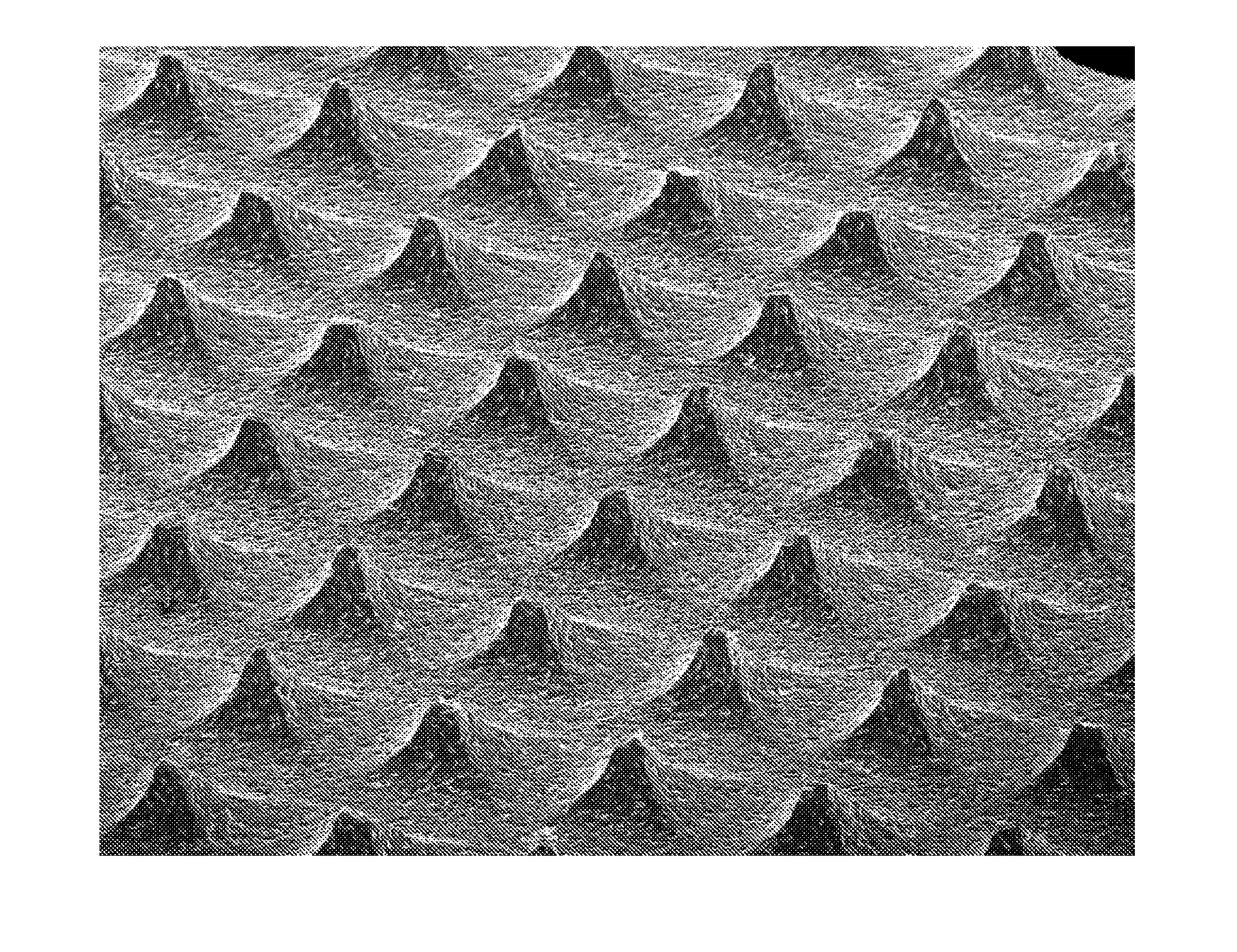
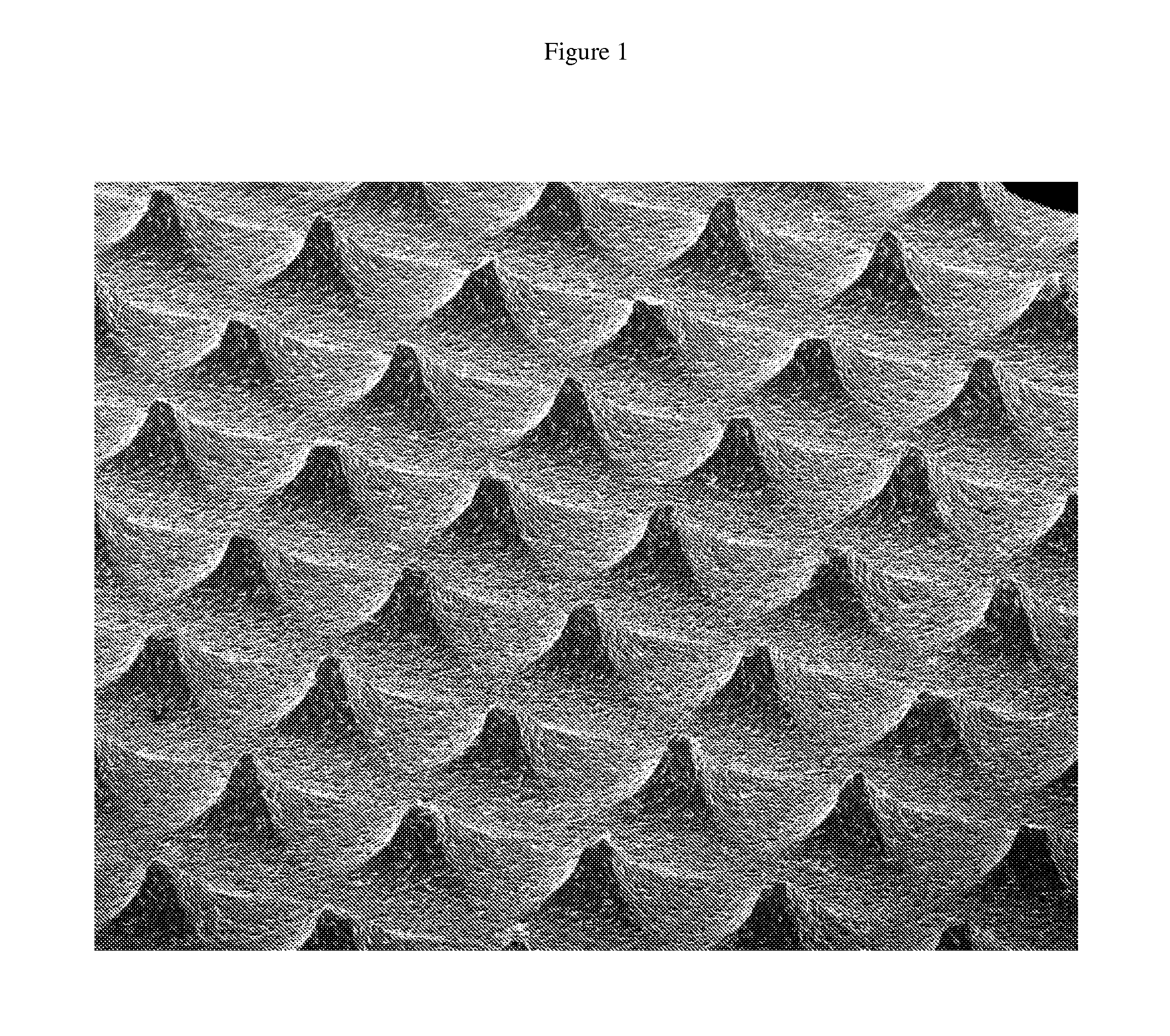
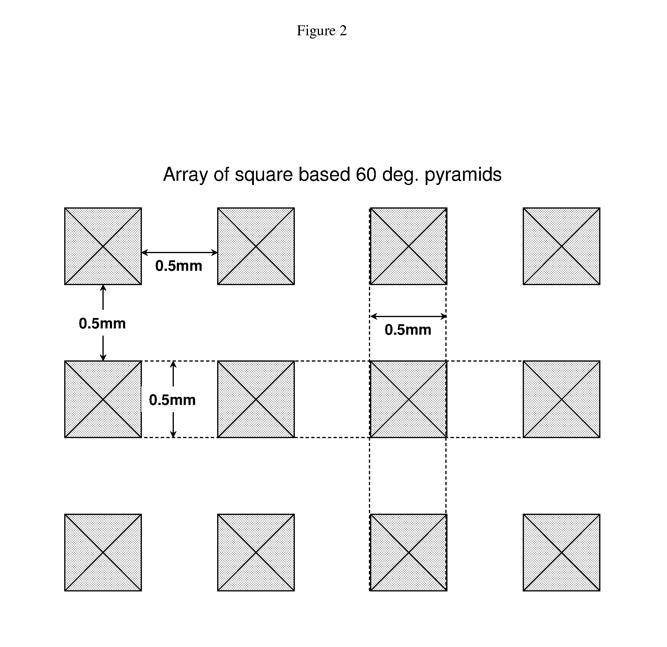
[0065]A CMP pad conditioner having the surface pattern shown in FIG. 2 was prepared by the following process. All machining was performed on a Fanuc Robocut alpha-oc wire EDM machine. In the wire EDM machine, a 0.008″ diameter wire was held in a vertical orientation, and a cylinder of SiC-diamond composite prepared according to Example 1 was mounted with the cylinder's axis in a horizontal orientation. A first cut was made perpendicular to the cylinder's axis, to expose a fresh surface of SiC-diamond composite.

[0066]A series of second cuts was then made into and across this fresh surface. This series of cuts consisted of a cut angled at 30 degrees, 0.5 mm into the surface of the sample; a cut 0.2 mm in length parallel to the surface of the sample at the 0.5 mm depth; and a subsequent cut at an angle of −30 degrees out of the surface. This series of cuts resulted in a trough in the surface of the SiC-diamond composite. A graphical representation of this cutting pattern is shown in FI...

example 3

[0068]A CMP pad conditioner having the surface pattern shown in FIG. 6 was prepared by the same process as in Example 2, except for the following differences.

[0069]A series of second cuts was then made into and across this fresh surface. This series of cuts consisted of a cut angled at −15 degrees, 0.5 mm into the surface of the sample; a cut 0.18 mm in length parallel to the surface of the sample at the 0.5 mm depth; and a subsequent cut at an angle of 15 degrees out of the surface. This series of cuts resulted in a trough in the surface of the SiC-diamond composite.

[0070]This series of cuts was repeated across the surface of the cylinder such that a series of parallel troughs were formed. Next, the cylinder was rotated by 120 degrees about its axis and a series of third cuts, identical to the series of second cuts, was made. Next, the cylinder was rotated again by 120 degrees and a series of fourth cuts, identical to the series of second and third cuts, leaving a matrix of triangu...


PUM

PropertyMeasurementUnit
temperatureaaaaaaaaaa

Abstract

The present disclosure provides a CMP pad conditioning tool with at least one integral abrasive protrusion. The present disclosure further provides a method for preparing this CMP pad conditioning tool, along with a method for using said tool to condition a CMP pad.

Description

TECHNICAL FIELD AND INDUSTRIAL APPLICABILITY[0001]The present disclosure provides a novel tool and method for reconditioning chemical mechanical polishing (“CMP”) pads. The present disclosure further includes methods for preparing the novel tool described herein as well as methods for using it.BACKGROUND OF THE INVENTION[0002]CMP methods are well known in the art and are regularly used to polish integrated circuit wafers. In a CMP process, polishing reactants, abrasives, and carrier fluids are applied to the wafer surface by a porous pad. Through a combination of chemical and mechanical action, the pad resurfaces the wafer being polished, such that a smooth wafer surface is obtained. In order to maintain the utility of the CMP pad, it must be periodically reconditioned to maintain uniform, repeatable polishing performance. This reconditioning may use a pad conditioning tool to remove spent reactants, abrasives, and polishing swarf.[0003]Various CMP pad conditioning tools are known i...

Claims


Application Information

Patent Timeline
Patent Type & Authority Applications(United States)
IPC IPC(8): B24B53/017B24B1/00
CPCB24B53/017B24D3/06B24D3/34B24D18/0054B24D18/0009B24D18/0027B24D7/02B24D18/00
Inventor RULAND, GARYSCHWEIZER, MARKRAREY, CHARLESEASLEY, THOMASGRAHAM, JAMES
Owner DIAMOND INNOVATIONS INC
Why Eureka
Try Eureka