Method for monitoring or tracing operations in well boreholes

a technology for tracing operations and wells, applied in the direction of wells/well accessories, instruments, nuclear radiation detection, etc., can solve the problems of high risk of radioactive material dispersion, high risk of health safety and environment perspectives, and the use of radioactive tracer materials for tracing the location of subsurface zones from hydraulic fracturing operations

Active Publication Date: 2012-07-12
MASNYK ROBERT MICHAEL +1
View PDF8 Cites 17 Cited by
  • Summary
  • Abstract
  • Description
  • Claims
  • Application Information

AI Technical Summary

Benefits of technology

[0007]In one embodiment, the present invention provides for a method for monitoring or tracing a job operation performed in a borehole characterized in that the method comprises: (a) disposing into the borehole a neutron absorber during the performance of the job operation; (b) logging the boreho...

Problems solved by technology

As a result, fractures are induced in stages along the length of a borehole, creating multiple reservoir zones along the borehole.
The use of radioactive tracer materials for tracing subsurface zone location from hydraulic fracturing operations poses a high risk from a health safety and environment (“HSE”) prospective.
The risk of dispersing radioactive material is high with respect to uncontrolled variables such as equipment failure leading to the release of ...

Method used


Image

  • Method for monitoring or tracing operations in well boreholes
  • Method for monitoring or tracing operations in well boreholes
  • Method for monitoring or tracing operations in well boreholes

Examples


example 1

Concept Verification

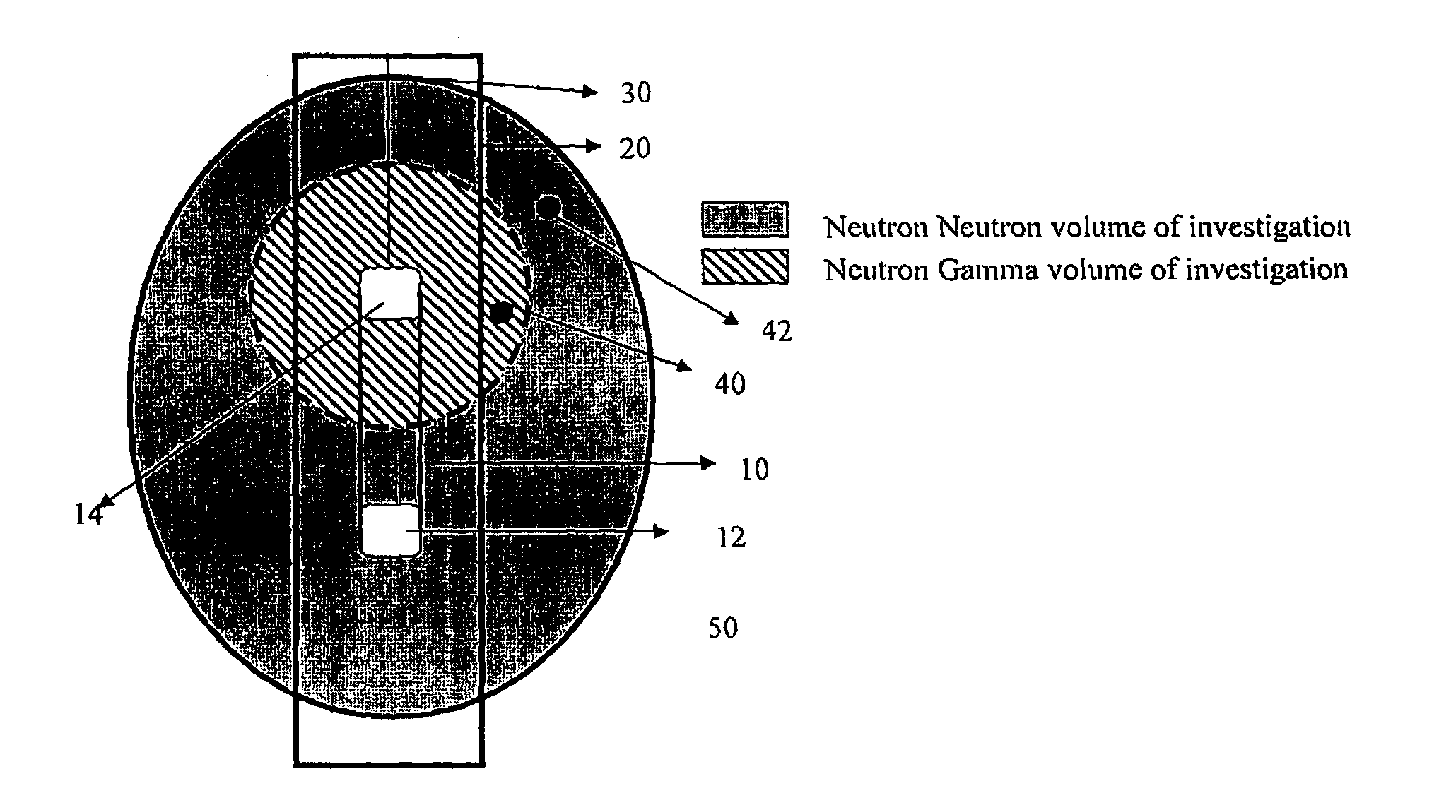
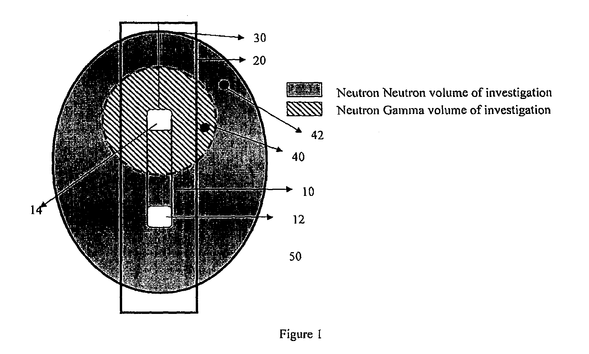
[0058]Theory: boron and cadmium have large thermal neutron cross-section capture area and emit a high energy gamma upon neutron capture.

[0059]Hypothesis: The presence of boron or cadmium should be detected by the decrease of neutron activity and the increase of high gamma energy.

[0060]Materials: 3-45 gallon drums; 5″ metal exhaust pipe; frac sand; boron carbide tag, logging device containing Am241Be neutron logging source, thermal neutron detector, neutron gamma detector and natural gamma detector.

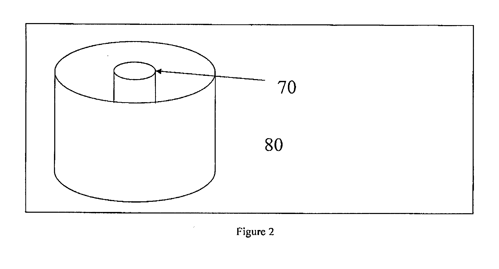
[0061]Method: Three 45 gallon metal barrels were cut in half 80 (refer to FIG. 2). A 5″ hole was cut in the center of the ends of each half barrel 80. A piece of 5″metal exhaust pipe 70 was inserted thru the hole into the half barrel 80. The 5″ exhaust pipe 70 was then welded onto the end of the barrel 80. Three of the half barrels 80 were filled completely with frac sand and fresh water. The remaining three barrels 80 were filled with tagged frac sand (at different con...

example 2

Demonstration Well Field Test

[0064]Hypothesis: Fracture tag relative placement to wellbore can be discerned by the relative changes in neutron neutron and neutron gamma responses with the presence of tag and the tagging and non-tagging of fracture stages should be easily recognizable.

[0065]Materials: B4C, Logging device containing Am241Be neutron logging source, thermal neutron detector, neutron gamma detector and natural gamma detector; wireline logging unit comprising of sufficient length electric wireline and an acquisition system to record the data.

[0066]Method: Record before frac neutron neutron, neutron gamma and natural gamma ray responses. Tag frac stages as follows: pad stage—no tag, proppant stage 1—tag front and back of stage at 375 g / m3 because it is believed that the initial stage of well fracturing will be up and down near wellbore. Therefore there is a possibility to detect the tagged and untagged stage if the vertical extent is high enough. Tagging the back of stage ...


PUM


Abstract

The present invention relates to novel methods for monitoring or tracing a job operation performed in a borehole, such as well boreholes traversing a geological formation. In one embodiment, the novel methods of the invention comprise the steps of: (a) disposing into the borehole a neutron absorber during the performance of the job operation; (b) logging the borehole with an instrument capable of measuring a neutron capture in and around the borehole after performance of the job operation; and (c) monitoring or tracing the job operation performed in the borehole by comparing the measured neutron capture with a baseline neutron capture in and around the borehole. The methods of the present invention pose small or no risk from a health safety and environment perspective and are useful for monitoring or tracing hydraulic fracturing, cementing operation in well boreholes, production logging or subsurface location of downhole collars, float shoes and other jewellery.

Description

FIELD OF THE INVENTION[0001]The present invention relates to novel methods for monitoring or tracing job operations in boreholes with the use of neutron absorbers such as boron and cadmium.BACKGROUND OF THE INVENTION[0002]It is oftentimes desirable to fracture boreholes in order to increase or restore the permeability of fluids such as oil, gas or water into the borehole thereby increasing the production of oil, gas, and / or water from the borehole. Hydraulic fracturing is a technique commonly used in the oil industry to create fractures that extend from an oil borehole into rock. Such fracturing is accomplished by injecting a suitable fracturing fluid within the borehole. Thereafter, sufficient pressure is applied to the fracturing fluid in order to cause the formation to break down with the attendant formation of one or more fractures therein. Simultaneously with or subsequent to the formation of the fracture a suitable carrier fluid having suspended therein a propping agent or pro...

Claims


Application Information

Patent Timeline
IPC IPC(8): G01V5/10G01V5/04
CPCE21B47/1015E21B43/26E21B47/11
Inventor MASNYK, ROBERT MICHAELKRAMER, HERMANN
Owner MASNYK ROBERT MICHAEL
Why Eureka
Try Eureka