receiver

a receiver and receiver technology, applied in the field of receivers, can solve the problems of unstable feedback signal fb, easy influence of control voltage signal v/sub>ctrl /sub>, etc., and achieve the effect of not reducing the quality of feedback signal

Inactive Publication Date: 2012-07-12
LIN TSUNG HSIEN
View PDF10 Cites 1 Cited by
  • Summary
  • Abstract
  • Description
  • Claims
  • Application Information

AI Technical Summary

Benefits of technology

[0009]The present invention employs the digital control oscillator to generate the feedback signal, thus it will not be influenced by the manufacturing processes and the noise, and the present invention will not decrease the quality of the feedback signal.

Problems solved by technology

However, since the gain of the VCO 112 is prone to be influenced by the change of the manufacture procedure, the voltage and the temperature, the feedback signal FB is unstable.
In addition, the control voltage signal VCTRL is also prone to be influenced by the noise of the DAC 110.

Method used


Image

  • receiver
  • receiver
  • receiver

Examples


Embodiment Construction

[0020]The present invention will now be described more specifically with reference to the following embodiments. It is to be noted that the following descriptions of preferred embodiments of this invention are presented herein for purpose of illustration and description only. It is not intended to be exhaustive or to be limited to the precise form disclosed.

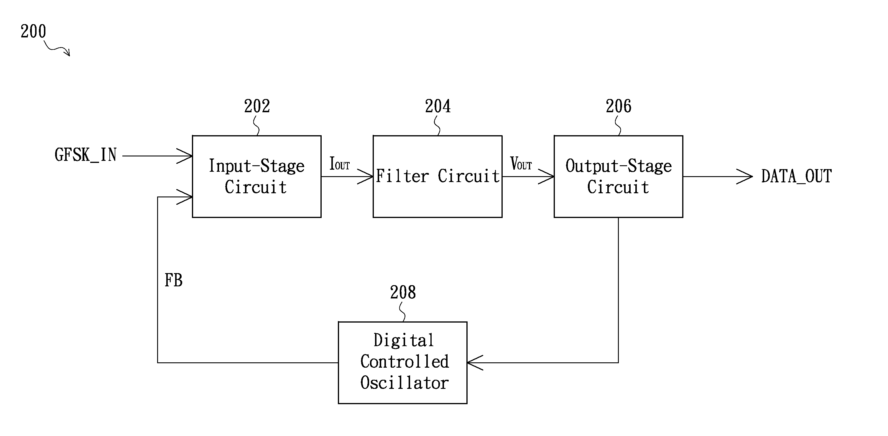
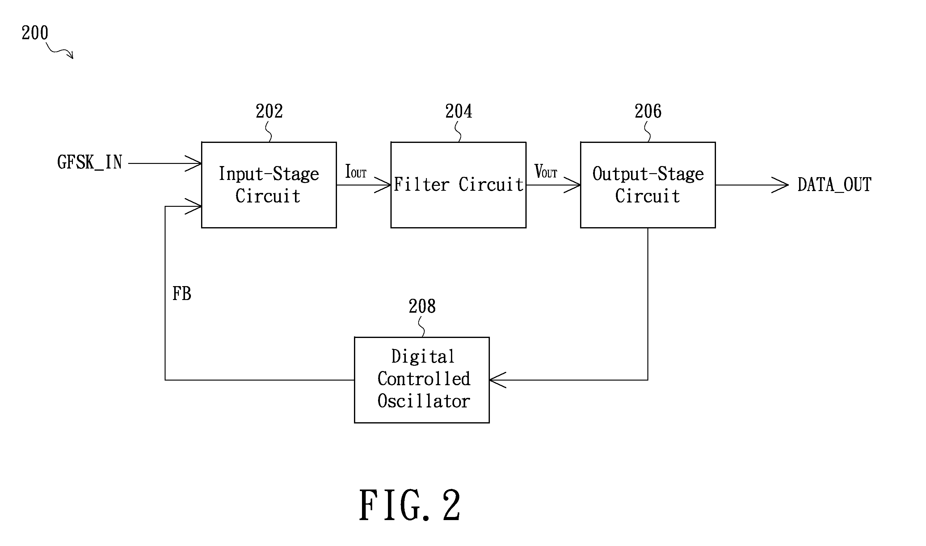
[0021]FIG. 2 is a system block schematic view of a receiver in accordance with an exemplary embodiment of the present invention. Referring to FIG. 2, the receiver 200 of the exemplary embodiment comprises an input-stage circuit 202, a filter circuit 204, an output-stage circuit 206 and a digital control oscillator 208. The input-stage circuit 202 is coupled to the filter circuit 204, and the filter circuit 204 is further coupled to the output-stage circuit 206. In the exemplary embodiment, an output terminal of the output-stage circuit 206 is used as an output terminal of the receiver 200. In addition, the output terminal of the ...


PUM


Abstract

A receiver comprises an input-stage circuit, a filter circuit, an output-stage circuit and a digital control oscillator. The input-stage circuit has a mixer configured for mixing the GFSK signal and a feedback signal to generate an input-stage current signal to the filter circuit. Then the filter circuit filters the input-stage current signal, and converts it into a voltage signal. The output-stage circuit is coupled to the filter circuit, for converting the voltage signal into a digital output data. In addition, the digital control oscillator is coupled to the output-stage circuit, for outputting the feedback signal based on the digital output data.

Description

FIELD OF THE INVENTION[0001]The present invention relates to a receiver, and more particularly to a receiver for receiving Gauss Frequency Shift Keying (GFSK) signals.BACKGROUND OF THE INVENTION[0002]FIG. 1 is a system block schematic view of a conventional GFSK receiver. Referring to FIG. 1, the conventional GFSK receiver 100 comprises a phase frequency detector (PFD) 102, a charge pump 104, a filter 106, a thermometer code generator 108, an analog-digital converter (DAC) 110 and a voltage controlled oscillator (VCO) 112. The PFD 102 is configured for receiving a GFSK signal GFSK_IN, and comparing it with a feedback signal FB to generate a comparison result. The comparison result will be transferred to the charge pump 104, to generate a voltage signal V1. Then the filter 106 filters the voltage signal V1 to eliminate noise, and transfers a corresponding filtered voltage signal V1′ to the thermometer code generator 108. Thus, the thermometer code generator 108 generates a digital ou...

Claims


Application Information

Patent Timeline
Patent Type & Authority Applications(United States)
IPC IPC(8): H04L27/14
CPCH04L27/2272H04L2027/0028H03D3/06H04L2027/0069H03D3/004H04L2027/0059
Inventor LIU, HUI-HSIENLIN, TSUNG-HSIENLIU, YAO-HONG
Owner LIN TSUNG HSIEN
Why Eureka
Try Eureka