Dual-purpose facility of continuous hot-dip coating and continuous annealing

a technology of hot-dip coating and continuous annealing, which is applied in the direction of heat treatment equipment, lighting and heating equipment, furnaces, etc., to achieve the effects of improving simplification, stabilizing the pressure balance of furnaces, and suppressing the gas in the atmospher

Active Publication Date: 2012-07-19
NIPPON STEEL CORP
View PDF5 Cites 9 Cited by
  • Summary
  • Abstract
  • Description
  • Claims
  • Application Information

AI Technical Summary

Benefits of technology

[0027]According to the dual-purpose facility of continuous hot-dip coating and continuous annealing according to (1), the directions in which the atmosphere gas flows in the annealing furnace are adjusted so as to be the same as each other when the facility is used as both the continuous hot-dip coated material production line and continuous annealed material production line. Further, in a case where uses in both the continuous hot-dip coated material production line and the continuous annealed material production line are compared, it is possible to make the discharge amounts of the gasses which are discharged from the outlet side of the annealing furnace approach each other. Thereby, it is possible to stabilize a furnace pressure balance when both lines are used. In addition, since it is possible to make the discharge amounts of the gasses which are discharged from the outlet side of the annealing furnace approach each other when both lines are used, even in a case so as to hold to the same pressure within the annealing furnace between the applications at both lines, it is possible to make the total supplying amounts of the atmosphere gasses to be supplied into the annealing furnace approach each other in the applications at both lines. To that extent, it is possible to suppress the atmosphere gas from being wastefully supplied. Particularly, since the operation which is necessary to obtain the effects can be only the opening and closing operation of the path on-off valve, it is possible to improve simplification and shortening of the line switching operation.
[0028]According to the dual-purpose facility of continuous hot-dip coating and continuous annealing according to (2), it is possible to make discharge amounts of the atmosphere gasses which are discharged from the outlet side of the annealing furnace to the outside of the furnace be the same extent as each other between when the facility is used as the continuous hot-dip coated material production line and when the facility is used as the continuous annealed material production line. As a result, it is possible to further reliably stabilize the furnace pressure balance in the annealing furnace when both lines are used. Thereby, operation conditions such as the ratio for each zone of the atmosphere gas supplied into the furnace or the total supplying amounts can be the same as each other at both lines. As a result, significant simplification or shortening of the line switching operation can be improved, adjustment errors of the operation conditions can be decreased, and therefore, stabilization of the operation can be improved. Particularly, after the discharge amount of the atmosphere gas is regulated by the flow rate regulating valve once, since the operation which is necessary for stabilizing the furnace pressure balance may be only the opening and closing operation of the path opening and closing unit, also from this point, simplification or shortening of the line switching operation can be improved.
[0029]According to the dual-purpose facility of continuous hot-dip coating and continuous annealing according to (3), it is possible to prevent a backflow of the outside air through the gas discharge path which is caused when change in the furnace pressure is generated during the operation of dual-purpose facility.
[0030]According to the dual-purpose facility of continuous hot-dip coating and continuous annealing according to (4), it is possible to prevent the backflow of the outside air through the gas discharge path while suppressing increases in the amount of the atmosphere gas to be supplied into the annealing furnace.
[0031]According to the dual-purpose facility of continuous hot-dip coating and continuous annealing according to (5), it is possible to suppress oxygen contained in the outside air or the like from penetrating into the annealing furnace through the gas discharge path due to diffusion.
[0032]According to the dual-purpose facility of continuous hot-dip coating and continuous annealing according to (6), it is possible to further effectively suppress oxygen contained in the outside air from penetrating into the annealing furnace through the gas discharge path due to diffusion.

Problems solved by technology

On the other hand, when the facility is used as the continuous annealed material production line, the steel strip bypasses the hot-dip coating bath and the hot-dip coating is not performed to the steel strip.

Method used


Image

  • Dual-purpose facility of continuous hot-dip coating and continuous annealing
  • Dual-purpose facility of continuous hot-dip coating and continuous annealing
  • Dual-purpose facility of continuous hot-dip coating and continuous annealing

Examples


first embodiment

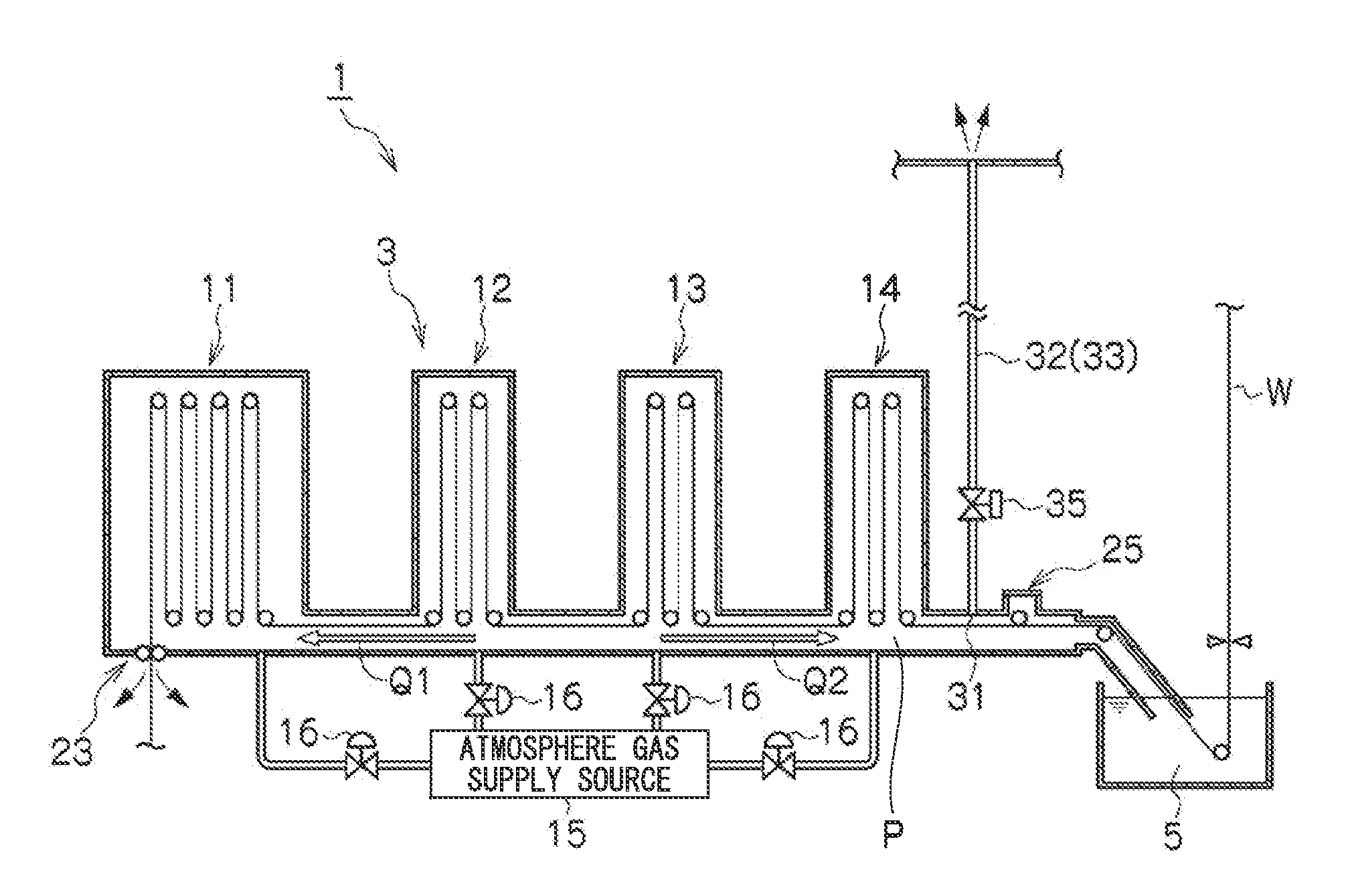
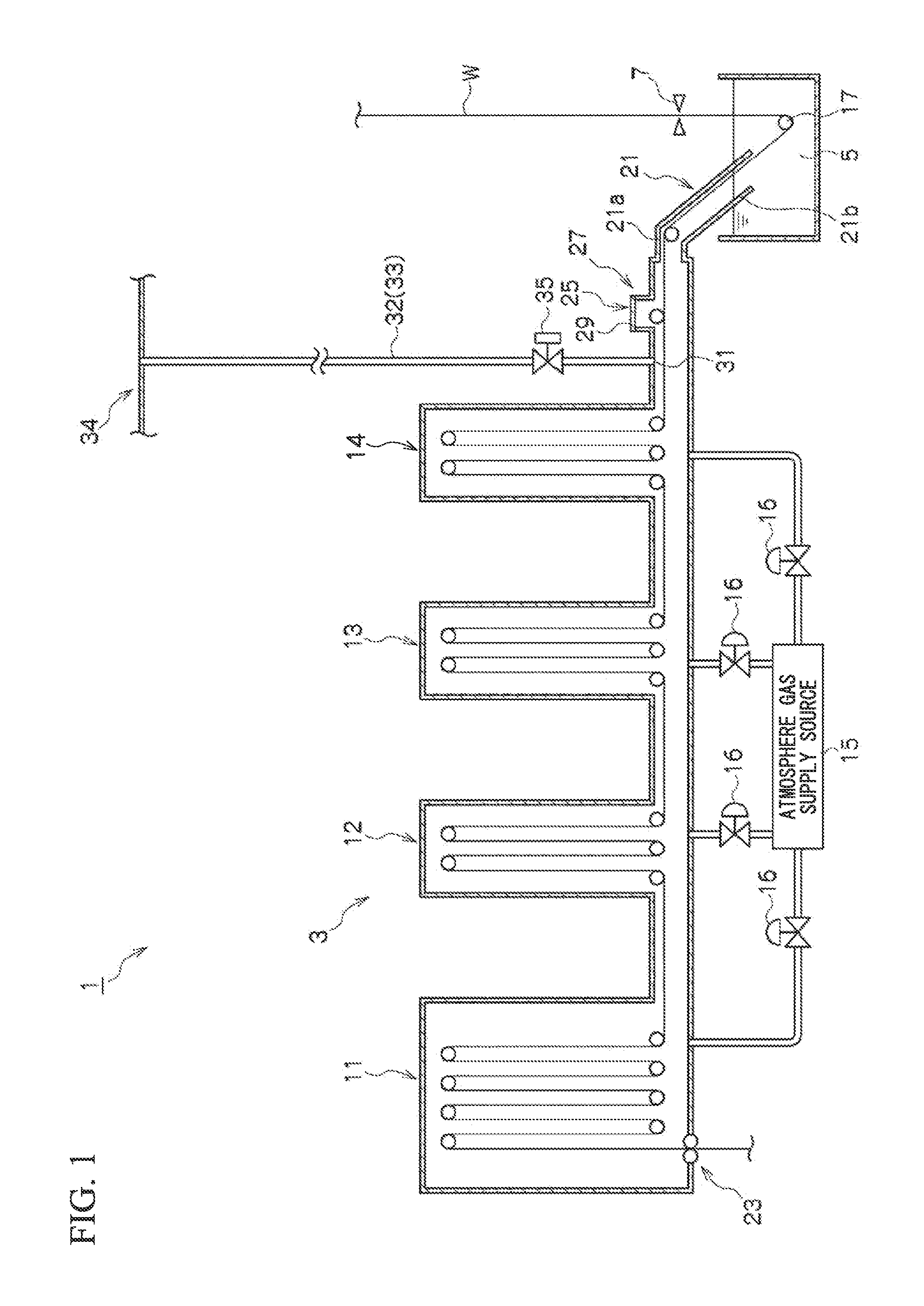
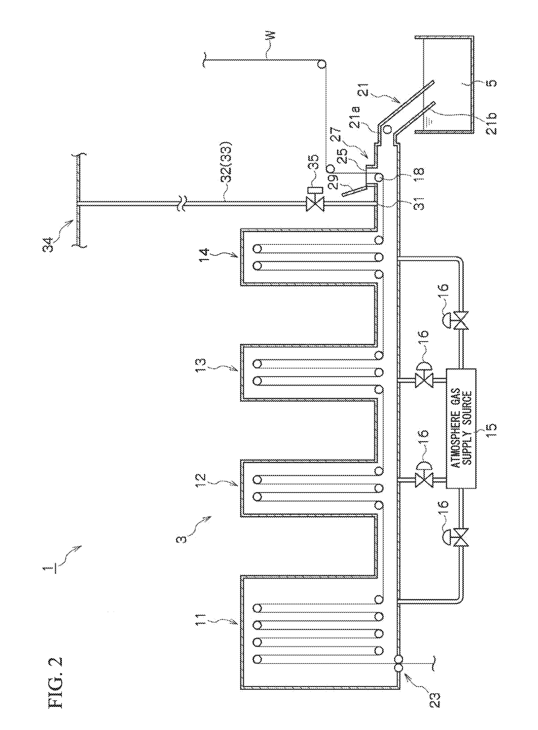
[0046]First, a first embodiment of the dual-purpose facility of continuous hot-dip coating and continuous annealing of the present invention (hereinafter, simply referred to as a “dual-purpose facility 1”) will be described. FIGS. 1 and 2 are longitudinal sectional views showing a schematic configuration of the dual-purpose facility 1 according to the present embodiment, FIG. 1 shows a configuration when the facility is used as the coated material production line, and FIG. 2 shows a configuration when the facility is used as the annealed material production line.

[0047]The dual-purpose facility 1 according to the present embodiment includes an annealing furnace 3 for annealing a steel strip W and a hot-dip coating bath5 for performing coating such as galvanizing to the steel strip W.

[0048]The annealing furnace 3 includes a heating zone 11 which heats the steel strip W, a soaking zone 12 which holds the heated steel strip W in a predetermined temperature range, and a slow cooling zone...

second embodiment

[0065]Next, a second embodiment of the dual-purpose facility of continuous hot-dip coating and continuous annealing according to the present invention will be described. Moreover, the components which are the same as those described in the first embodiment are denoted by the same reference symbols, and the descriptions are omitted below.

[0066]FIG. 5 is a longitudinal sectional view showing a schematic configuration of a dual-purpose facility 201 of continuous hot-dip coating and continuous annealing according to the present embodiment.

[0067]In addition to the components of the dual-purpose facility 1 described in the first embodiment, the dual-purpose facility 201 according to the present embodiment further includes a flow rate regulating valve 37 which is disposed in the gas discharge path 33 and is a flow rate regulating unit for regulating the flow rate of the gas which flows in the gas discharge path 33, and a plurality of pressure gauges 38 which are units for measuring the pre...

third embodiment

[0074]A third embodiment of the dual-purpose facility of continuous hot-dip coating and continuous annealing according to the present invention will be described. In addition, the components which are the same as those described in the first embodiment are denoted by the same reference symbols, and the descriptions are omitted below.

[0075]FIG. 6 is a longitudinal sectional view showing a schematic configuration of a dual-purpose facility 301 of continuous hot-dip coating and continuous annealing according to the present embodiment.

[0076]In addition to the components of the dual-purpose facility 1 described in the first embodiment, the dual-purpose facility 301 according to the present embodiment further includes an ejector 39 which is disposed in the gas discharge path 33 and a cyclone 45 which is disposed in the gas discharge path 33.

[0077]The ejector 39 is a gas suction unit which suctions the atmosphere gas in the annealing furnace 3 and discharges this toward the outside of the ...


PUM

PropertyMeasurementUnit
thicknessaaaaaaaaaa
furnace pressure P2aaaaaaaaaa
pressureaaaaaaaaaa

Abstract

A dual-purpose facility of continuous hot-dip coating and continuous annealing is configured so as to be switched between a continuous hot-dip coated material production line and a continuous annealed material production line, and includes a gas discharge path that discharges atmosphere gas in an annealing furnace from a gas discharge port provided in an outlet side of the annealing furnace out of the annealing furnace and a path opening and closing unit for opening and closing the gas discharge path. The path opening and closing unit opens the gas discharge path when the dual-purpose facility is used as the continuous hot-dip coated material production line and closes the gas discharge path when the dual-purpose facility is used as the continuous annealed material production line.

Description

FIELD OF THE INVENTION[0001]The present invention relates to a dual-purpose facility of continuous hot-dip coating and continuous annealing which is configured so as to switch a continuous hot-dip coated material production line and a continuous annealed material production line.[0002]Priority is claimed on Japanese Patent Application No. 2009-229519, filed Oct. 1, 2009, the content of which is incorporated herein by reference.DESCRIPTION OF RELATED ART[0003]In conventional techniques, from the viewpoint of improving economic efficiency, a dual-purpose facility is suggested which switches a continuous hot-dip coated material production line for a coated steel sheet and a continuous annealed material production line for a cold-rolled steel sheet and can operate through a single facility. In the dual-purpose facility, when the facility is used as the continuous hot-dip coated material production line, a steel strip is immersed into a hot-dip coating bath and the hot-dip coating is per...

Claims


Application Information

Patent Timeline
Patent Type & Authority Applications(United States)
IPC IPC(8): B05C11/00B05C3/02
CPCC21D9/56C21D9/667F27B9/3011F27B9/28C23C2/003C23C2/00344C23C2/004C23C2/0035C23C2/0038C23C2/52C23C2/00F27D7/06B05C3/02B05C3/125B05C3/132
Inventor HOSHINO, MASANORI
Owner NIPPON STEEL CORP
Why Eureka
Try Eureka