

Commutated electric drive and method for controlling a commutated electric motor
- Summary
- Abstract
- Description
- Claims
- Application Information
AI Technical Summary
Benefits of technology
Problems solved by technology
Method used
Image

Examples
Embodiment Construction
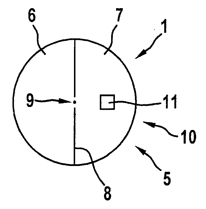
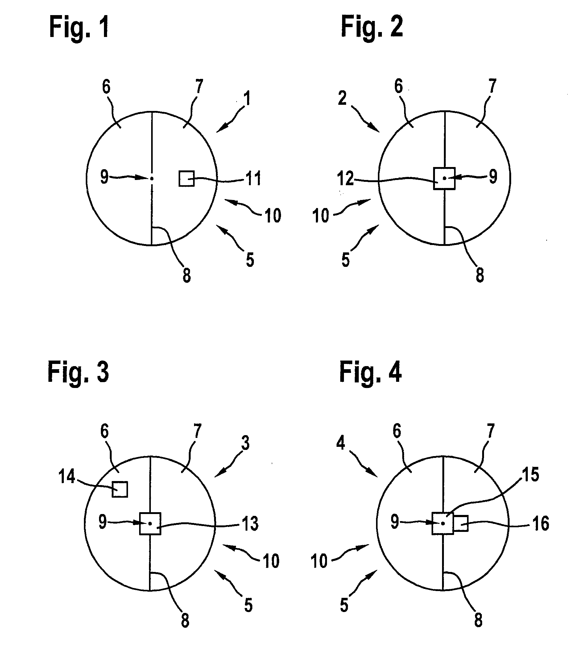
[0023]A commutated electric drive according to the present invention, having an electric motor including a sensor assembly, has a magnetic field generator, in particular a permanent magnet, on a shaft of the electric motor. Magnetic sensors are situated stationary relative to a stator of the motor opposite to the magnetic field generator rotating together with the shaft. FIGS. 1 through 4 schematically show different specific embodiments of sensor assemblies 1, 2, 3, 4 according to the present invention, each in side view from a front face of the motor shaft, the magnetic field generator being a permanent magnet here, and the shared elements of the specific embodiments being cited first. Permanent magnet 5 having poles 6 and 7, identified by pole separation line 8, is situated on motor shaft 10 symmetrically relative to shaft center 9. For this purpose, the types and positions of the magnetic sensors are shown.
[0024]FIG. 1 shows a sensor assembly 1 according to the present invention...
PUM
 Abstract
Description
Claims
Application Information