
Airborne lidar for detecting matter suspended in air

a technology of airborne lidar and suspended matter, which is applied in the direction of instruments, using reradiation, transportation and packaging, etc., can solve the problems of inability to distinguish between components, ineffective for detecting such minute particles as ice crystals and volcanic ash, and inability to cover the entire flight area from the standpoint of cost-effectiveness, so as to shorten shorten the effect of time and shortening the period between engine inspection

Inactive Publication Date: 2012-07-19
JAPAN AEROSPACE EXPLORATION AGENCY
View PDF6 Cites 20 Cited by
  • Summary
  • Abstract
  • Description
  • Claims
  • Application Information

AI Technical Summary

Benefits of technology

[0016]Further, at high altitudes such as those at which passenger jets cruise, the air is generally stable, and so suspended matter is often spread out in layer form at fixed altitudes. Hence rather than avoiding detected dangerous matter by means of a steep turn, it is more realistic to either not fly at a particularly dangerous altitude, or to pass through a dangerous altitude in a short time. When avoidance is not possible, by integrating the amount of volcanic ash sucked in, it is possible to utilize the result to shorten the period between engine inspections or to make other similar decisions. Hence LIDAR for detection of matter suspended in air of this invention can be expected to effectively prevent aircraft accidents and damage to flight equipment.

Problems solved by technology

Air turbulence is representative of threats to the flight of aircraft posed by meteorological phenomena, but in addition to this there are such dangerous atmospheric states as ice crystals and volcanic ash, and insofar as such phenomena cannot be detected using weather radar, they remain obstacles to flight.
Using Doppler LIDAR, it is possible to measure the spatial distribution of aerosols, but aerosol components cannot be measured, and so it is not possible to distinguish between components such as water droplets that are not dangerous to the flight of an aircraft, and components such as ice crystals and volcanic ash that are very dangerous.
Further, weather radar which has already been utilized in aircraft-mounted mode uses microwaves with wavelengths of several centimeters, and so are not effective for detecting such minute particles as ice crystals and volcanic ash.
Observation of the upper atmosphere from ground facilities, and observation from artificial satellites, are possible; but covering the area of an entire flight is not realistic from the standpoint of cost-effectiveness.
Moreover, All Nippon Airways Flight 173 on May 21, 2001, and Japan Airlines Flight 2408 on Sep. 23, 2004, are thought to be accidents due to air turbulence, but if ice crystals in the upper portion of a cumulonimbus cloud had been detected in advance, there was the possibility that air turbulence could have been predicted.
In addition, there exist numerous examples in which it is suspected that ice crystals may be related to crash accidents with unknown causes.
In addition to ice crystals, volcanic ash is also extremely dangerous as suspended matter which is a threat to aircraft.
However, the function of such centers is to monitor volcanic ash, predict dispersion of volcanic ash, and provide a broad range of other information, but not to provide detailed information for individual aircraft.
When an engine sucks in volcanic ash, even when an accident does not result, expensive repair costs are incurred, and considerable damage has occurred in Japan as well due to the volcanic fumes from Sakurajima and Miyakejima.
In April 2010, a volcano in the south of Iceland erupted, and large amounts of volcanic ash were spewed upward; at high altitudes where the atmosphere is stable, there is the possibility that volcanic ash may remain at a specific height for a long period of time.
Because in this case the dangerous region of airspace could not be determined precisely, it was necessary to completely halt flights over Europe as a whole, causing massive economic losses worldwide.
Although lightning strikes of aircraft, which occur regularly, will never result in a major accident, damage to flight equipment frequently occurs.

Method used


Image

  • Airborne lidar for detecting matter suspended in air
  • Airborne lidar for detecting matter suspended in air
  • Airborne lidar for detecting matter suspended in air

Examples


example 1

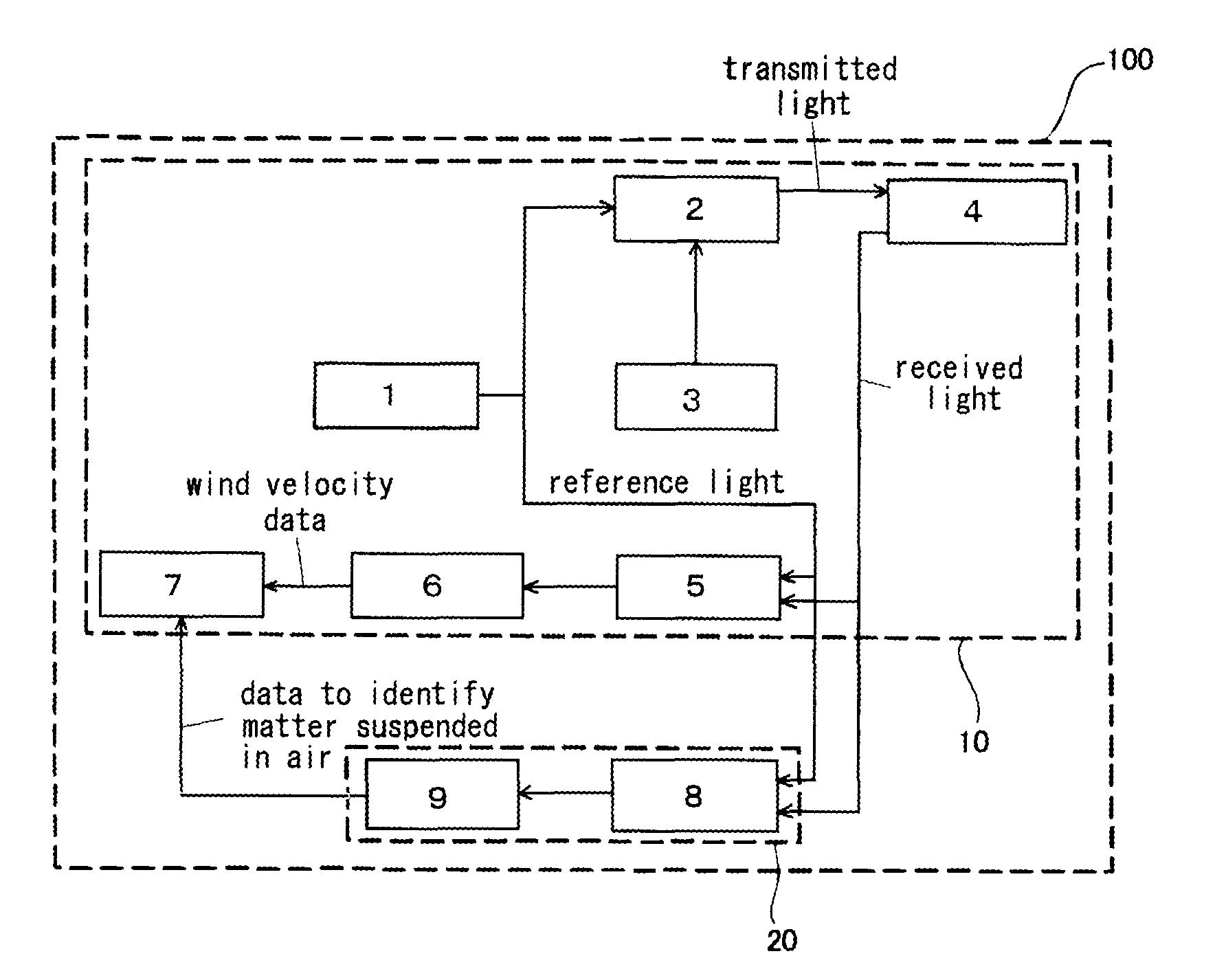
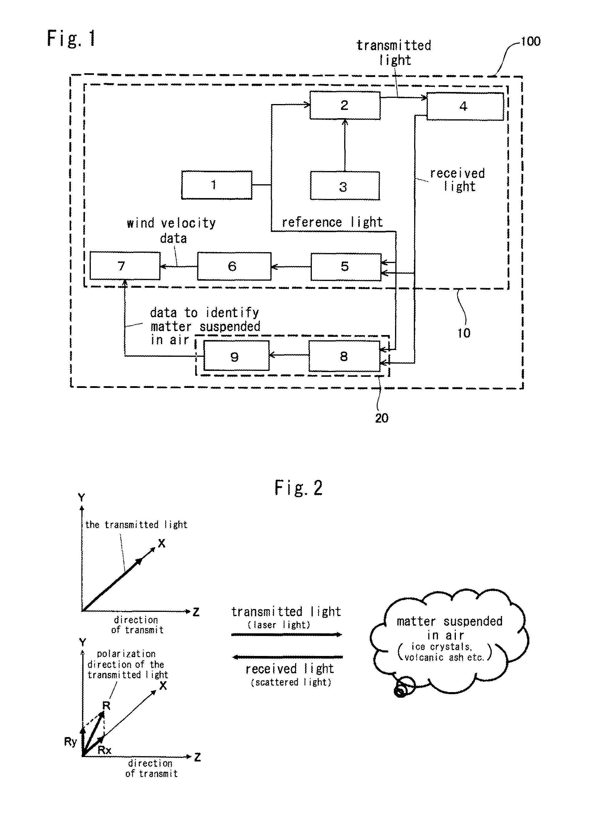
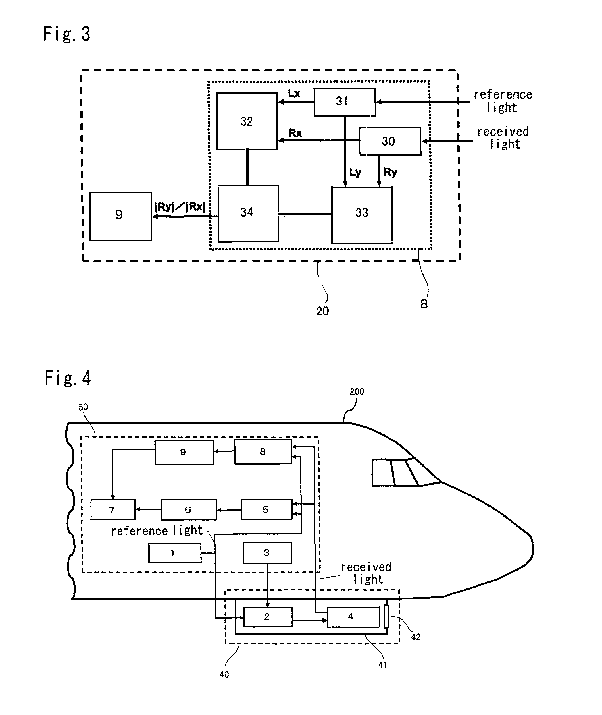
[0037]FIG. 4 shows a state in which LIDAR for detection of matter suspended in air of this invention is mounted on an aircraft. In the figure, an optical telescope and an optical amplifier are mounted on the lower face of the airframe, and devices outside the airframe are covered by a fairing 41 for the purpose of reducing air friction and the like. A window 42 is installed in the direction in which laser light is transmitted, so that laser light can be transmitted and scattered light can be received. In this example, a configuration is employed in which the optical telescope and optical amplifier are mounted on the lower face of the airframe, but other configurations are possible, and mounting on side faces of the nose, on lower faces of the wings, and similar are conceivable; equipment can be mounted on individual aircraft at locations where mounting is easy. Equipment other than that described above is mounted within the aircraft.

[0038]In identification of the components of matte...

example 2

[0042]FIG. 5 explains an example in a case in which there exists a region in which the reception intensity of LIDAR is inverted according to distance. Normally the reception intensity of scattered light declines with distance, but the focal length of the optical system is set in the range from 2 km to infinity, and at close distances, efficient reception is not possible even at high scattered light intensity, so that the reception intensity declines. If this region is region A, then region A is specific to the device and is limited at close distances; hence even when there is inversion in region A, the inversion can be ignored.

[0043]On the other hand, regarding region B in which reception intensity is inverted far away, it is thought that matter which strongly scatters laser light is suspended. However, attenuation of the laser light due to the existence of this matter is also large, and so the entire region in which matter is suspended cannot be observed, and what can be observed i...

example 3

[0045]FIG. 6 is an explanatory diagram of the configuration of the LIDAR for detection of matter suspended in air of Example 3. In this LIDAR for detection of matter suspended in air 100, the transmission side comprises a reference light source 1b which uses a laser diode or similar to generate laser light (reference light) which becomes transmitted light, and an optical telescope 4 which radiates the transmitted light output from the reference light source 1b to a great distance and which concentrates scattered light from a great distance. When Doppler LIDAR is used to detect air turbulence, it is necessary to observe light scattered by aerosols suspended in a high-altitude region extending at most several tens of kilometers in a remote region and at an altitude of 10 km or higher, and in order to detect wind velocity accompanying air turbulence with good precision, an optical amplifier must be used to increase the output of transmitted light; but when specializing for a function t...


PUM

PropertyMeasurementUnit
depolarization ratioaaaaaaaaaa
wavelength bandaaaaaaaaaa
depolarization ratioaaaaaaaaaa

Abstract

An object of the present invention is to provide a device which detects matter suspended in air, represented by, for example, ice crystals, volcanic ash, in the forward direction of the flight of an aircraft. A method of detecting matter suspended in air of this invention is characterized in that, in airborne Doppler LIDAR using laser light, components of matter subjected to laser light reflection and scattering are remotely measured on a basis of an angular difference in planes of polarization of transmitted light which is laser light radiated into the atmosphere, and received light scattered by matter suspended in air in a remote region.

Description

BACKGROUND OF THE INVENTION[0001]1. Field of the Invention[0002]This invention relates to LIDAR technology for detecting matter suspended in air, utilized by an aircraft to measure components of matter suspended in air in distant regions ranging from several hundred meters to approximately several tens of kilometers based on the depolarization ratio of laser light, when laser light is irradiated into the atmosphere and the scattered light resulting from scattering of the laser light in the atmosphere is received.[0003]2. Description of the Related Art[0004]Air turbulence is representative of threats to the flight of aircraft posed by meteorological phenomena, but in addition to this there are such dangerous atmospheric states as ice crystals and volcanic ash, and insofar as such phenomena cannot be detected using weather radar, they remain obstacles to flight. The inventors have been engaged in research and development of Doppler LIDAR using laser light as a means of preventing acci...

Claims


Application Information

Patent Timeline
Patent Type & Authority Applications(United States)
IPC IPC(8): G01N21/49G01N21/21G01N21/55B64D45/00G01S7/51G01S17/58G01S17/95G01V8/12G01W1/00
CPCG01S17/95G01S7/499Y02A90/10
Inventor ASAHARA, TAKASHIINOKUCHI, HAMAKIASAI, KAZUHIRO
Owner JAPAN AEROSPACE EXPLORATION AGENCY
Learn More