
Magnetic recording medium

a recording medium and magnetic technology, applied in the field of magnetic recording mediums, can solve the problems of compromising recording properties, compromising the reliability of reproduced signals, and recording attenuation, and achieve the effect of good recording properties and high thermal stability in a magnetic layer

Inactive Publication Date: 2012-07-19
FUJIFILM CORP
View PDF8 Cites 123 Cited by
  • Summary
  • Abstract
  • Description
  • Claims
  • Application Information

AI Technical Summary

Benefits of technology

[0010]Accordingly, an aspect of the present invention provides for a particulate magnetic recording medium affording good recording properties and containing magnetic particles of high thermal stability in a magnetic layer.
[0012]Exchange-coupling a soft magnetic material (also referred to as a “soft magnetic phase” hereinafter) to the surface of a hard magnetic particle (also referred to as a “hard magnetic phase” or “hard magnetic material” hereinafter) having high crystal magnetic anisotropy (a high Ku) results in the soft magnetic phase responding first to changes in the external magnetic field, changing the orientation of the spin of the soft magnetic phase. That makes it possible to change the orientation of spin of the hard magnetic phase that is exchange-coupled with the soft magnetic phase, permitting a lower switching magnetic field while maintaining the thermal stability of the hard magnetic particle in the magnetic particle. As a result, it becomes possible to achieve good recording properties in a magnetic layer containing magnetic particles of high thermal stability.
[0036]The present invention makes it possible to achieve good recording properties in a magnetic recording medium exhibiting high reliability by incorporating magnetic powder of high thermal stability into the magnetic layer.

Problems solved by technology

However, when the magnetic particles contained in the magnetic recording layer of a magnetic recording medium are of poor thermal stability, the energy that maintains the direction of magnetization of the magnetic particles (the magnetic energy) cannot readily counter thermal energy, and the information that has been recorded attenuates over time (magnetic attenuation), ultimately compromising the reliability of the reproduced signal.
Although materials of high crystal magnetic anisotropy afford good thermal stability, an increase in the switching magnetic field necessitates a large external magnetic field for recording, compromising recording properties.
From the perspective of maintaining the general-purpose properties of such particulate media, it is difficult in practical terms to employ a magnetic material in which expensive Pt is used.
By contrast, it is difficult to apply Technique 2 to particulate magnetic recording media for the purpose of improvement of recording properties.
The reason is that it is practically impossible to apply Technique 2 to nonmagnetic organic material supports usually employed in particulate magnetic recording media because these supports are of poorer heat resistance.
As set forth above, it is difficult to provide a particulate magnetic recording medium affording good recording properties using magnetic particles of high thermal stability with the conventional art.

Method used


Image

  • Magnetic recording medium

Examples


examples

[0130]The present invention will be described in detail below based on Examples. However, the present invention is not limited to the examples.

reference examples 1 to 8

Preparation Examples Employing Nd2Fe14B as the Hard Magnetic Phase

[0131]Magnetic powder comprised of gathering hard magnetic particles of Nd2Fe14B composition that had been prepared by HDDR method (Hc: 734 kA / m, saturation magnetization: 1.42×10⁻¹ A·m2 / g (142 emu / g), average crystal particle diameter: 100 nm) was immersed in the salt solution (0.5 g of solution per gram of magnetic powder) indicated in Table 1 in such a manner as to wet the surface of the particles, and heated to 110° C. in a nitrogen atmosphere to remove the solvent. In this process, the particles in the salt solution were stirred once every 30 minutes.

[0132]The dry powder obtained by removing the solvent was processed for one hour at 400° C. in a hydrogen gas flow to subject to reductive decomposition the Fe salt contained in the deposition on the surface of the particles. During reductive decomposition, the hydrogen gas that was discharged contained by-products during the course of salt decomposition, and was thu...

reference examples 9 to 12

Preparation Examples Employing Barium Ferrite as the Hard Magnetic Phase

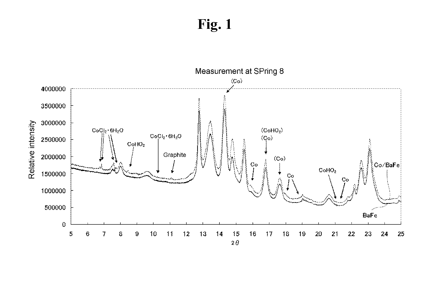
[0146]Magnetic powder comprised of gatheing particles of barium ferrite (referred to as “BaFe” hereinafter) (Hc: 270 kA / m, saturation magnetization: 5.2×10⁻² A·m2 / g (52 emu / g), average plate diameter: 35 nm, average plate thickness: 8 nm) was immersed in the salt solution (1 gram of solution per gram of BaFe powder) described in Table 2 so as to wet the surface of the particles. The solvent was removed while reducing the pressure with an aspirator. In this process, the particles in the salt solution were stirred once every 30 minutes.

[0147]The dry powder obtained by removing the solvent was processed for one hour at 400° C. in a 4 volume percent methane 96 volume percent nitrogen gas flow to conduct reductive decomposition of the Co salt or the Fe salt contained in the deposition of the particle surface.

[0148]The above step yielded a magnetic powder comprised of gathering core / shell magnetic particles with cores...


PUM


Abstract

An aspect of the present invention relates to a magnetic recording medium comprising a magnetic layer containing a ferromagnetic powder and a binder on a nonmagnetic support, wherein the ferromagnetic powder is comprised of magnetic particles comprising a hard magnetic particle and a soft magnetic material deposited on a surface of the hard magnetic particle in a state where the soft magnetic material is exchange-coupled with the hard magnetic particle.

Description

CROSS-REFERENCE TO RELATED APPLICATIONS[0001]This application claims the benefit of priority under 35 USC 119 to Japanese Patent Application No. 2011-006556 filed on Jan. 17, 2011 and Japanese Patent Application No. 2011-239571 filed on Oct. 31, 2011, which are expressly incorporated herein by reference in their entirety.BACKGROUND OF THE INVENTION[0002]1. Field of the Invention[0003]The present invention relates to a magnetic recording medium, and more particularly, to a particulate magnetic recording medium affording both good recording properties and high reliability.[0004]2. Discussion of the Background[0005]Due to increases in the quantity of information being recorded, higher density recording is being constantly demanded of the magnetic recording media widely employed as video tapes, computer tapes, and disks. However, when the magnetic particles contained in the magnetic recording layer of a magnetic recording medium are of poor thermal stability, the energy that maintains t...

Claims


Application Information

Patent Timeline
Patent Type & Authority Applications(United States)
IPC IPC(8): G11B5/65
CPCG11B5/712G11B5/7085
Inventor HATTORI, YASUSHISUZUKI, RYOTAKASADA, NORIHITO
Owner FUJIFILM CORP
Learn More