Schottky diode having a substrate p-n diode

a diode and substrate technology, applied in the direction of basic electric elements, electrical equipment, semiconductor devices, etc., can solve the problems of high forward voltage uf, non-negligible efficiency loss, and the inability of schottky diodes to be used in motor-vehicle generator systems, etc., to achieve low forward voltage, reduce the effect of forward voltage and greater robustness

Inactive Publication Date: 2012-07-26
ROBERT BOSCH GMBH
View PDF5 Cites 5 Cited by
  • Summary
  • Abstract
  • Description
  • Claims
  • Application Information

AI Technical Summary

Benefits of technology

[0015]According to the present invention, Schottky diodes having a low reverse current, lower forward voltage, greater robustness and simpler process control shall be provided, which are suited for use as power Zener diodes in motor-vehicle generator systems.

Problems solved by technology

The main disadvantage is the high forward voltage UF.
At room temperature, current only begins to flow at UF=0.7 V. Under normal operating conditions, for instance, at a current density of 500 A / cm2, UF increases to greater than 1 V, which means a non-negligible loss of efficiency.
However, at present, Schottky diodes are not yet used in motor-vehicle generator systems.
This may be attributed to a few crucial disadvantages of Schottky diodes: 1) higher reverse current in comparison with p-n diodes, 2) strong dependence of the reverse current on the reverse voltage, and 3) poor robustness, especially at high temperatures.
Because of the radial extension of the space charge regions, this shape of p-wells does not produce a highly effective blocking-out of the Schottky effect.
It is not possible to strengthen the blocking effect by deeper p-diffusion alone, since the lateral diffusion simultaneously becomes correspondingly wider, as well.

Method used


Image

  • Schottky diode having a substrate p-n diode
  • Schottky diode having a substrate p-n diode
  • Schottky diode having a substrate p-n diode

Examples


Embodiment Construction

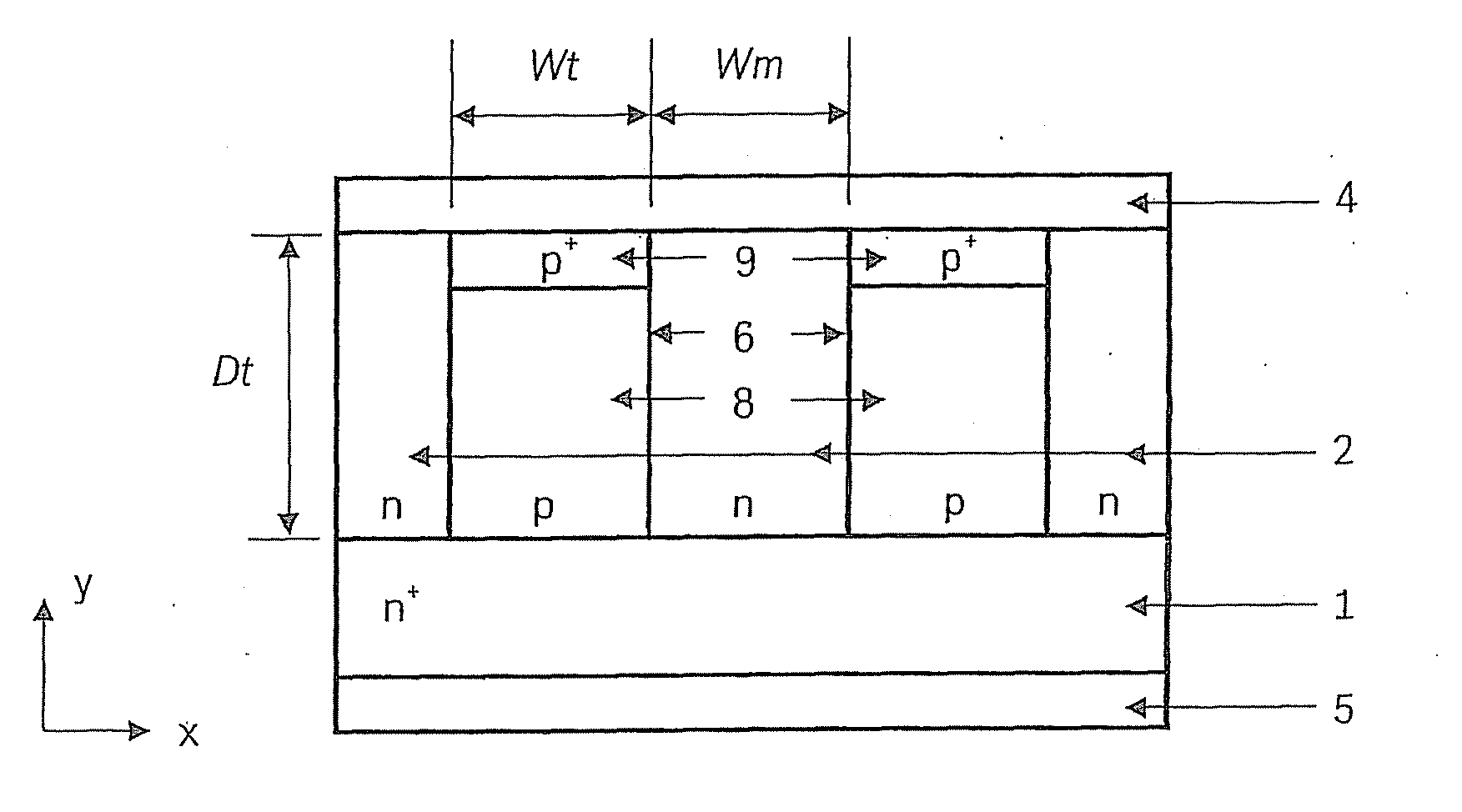
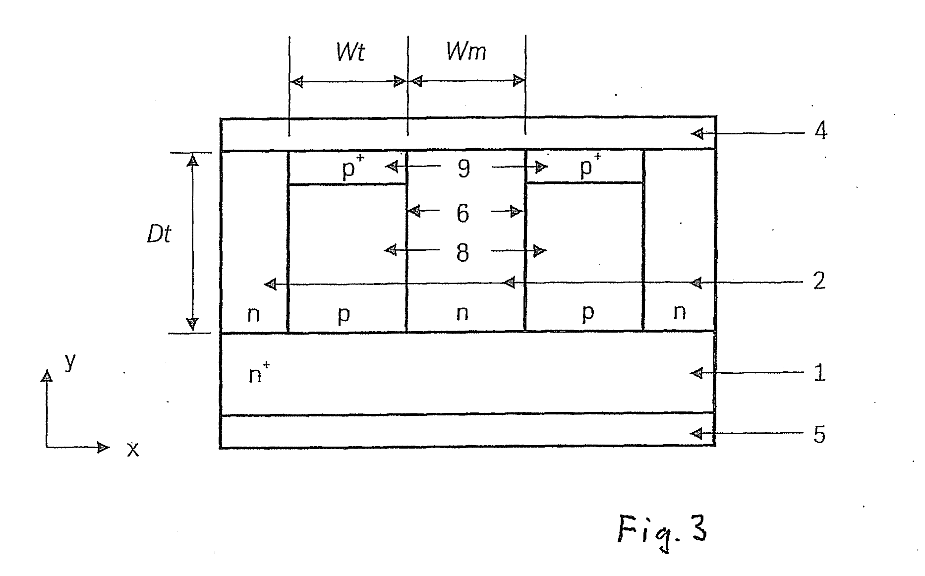
[0020]As shown in FIG. 3, the TJBS-Sub-PN of the present invention is made up of an n+-substrate 1, an n-epitaxial layer 2, at least two trenches 6 that are etched through epitaxial layer 2 up to n+-substrate 1 and have a width Wt, a depth Dt and a distance Wm between adjacent trenches 6, and metallic layers on the front side of the chip 4 in the form of an anode electrode and on the back side of the chip 5 in the form of a cathode electrode. Trenches 6 are filled in with p-doped Si or poly-Si 8, and additional, thin p+-layers 9 are situated in the upper regions of the trenches to provide ohmic contacts with metallic layer 4. In some instances, thin p+-layers 9 may also be somewhat recessed, so that they are situated completely within p-doped layers 8.

[0021]In electrical terms, the TJBS-Sub-PN is a combination of a Schottky diode (Schottky barrier between metallic layer 4 as an anode and n-epitaxial layer 2 as a cathode), an epitaxial p-n diode (p-n junction between the p-wells (the...


PUM


Abstract

A semiconductor device has a trench junction barrier Schottky diode that includes an integrated substrate p-n diode (TJBS-Sub-PN) as a clamping element, the trench junction barrier Schottky diode being suited, e.g., as a Zener diode having a breakdown voltage of approximately 20 V, for use in motor-vehicle generator systems. In this context, the TJBS-Sub-PN is made up of a combination of a Schottky diode, an epitaxial p-n diode and a substrate p-n diode, and the breakdown voltage of the substrate p-n diode (BV_pn) is less than the breakdown voltage of the Schottky diode (BV_schottky) and the breakdown voltage of the epitaxial p-n diode (BV_epi).

Description

BACKGROUND OF THE INVENTION[0001]1. Field of the Invention[0002]The present invention relates to a trench junction barrier Schottky diode having an integrated substrate p-n diode as a clamping element (referred to below in simplified terms as TJBS-Sub-PN), which is suitable, e.g., as a power Zener diode having a breakdown voltage of approximately 20 V for use in motor-vehicle generator systems.[0003]2. Description of Related Art[0004]In modern motor vehicles, more and more functions are implemented by electrical components. This creates a continuously increasing requirement for electrical power. In order to satisfy this requirement, the efficiency of the generator system in the motor vehicle must be increased. To this day, p-n diodes have normally been used as Zener diodes in motor-vehicle generator systems. Advantages of p-n diodes include, on one hand, the low reverse current and, on the other hand, the high degree of robustness. The main disadvantage is the high forward voltage U...

Claims


Application Information

Patent Timeline
Patent Type & Authority Applications(United States)
IPC IPC(8): H01L27/07H01L21/822
CPCH01L29/872H01L29/861H01L21/18
Inventor QU, NINGGOERLACH, ALFRED
Owner ROBERT BOSCH GMBH
Why Eureka
Try Eureka