Torsion vibration damper and damping device and torque transmission device

a technology of torque transmission device and damper, which is applied in the direction of mechanical hybrid vehicles, mechanical apparatus, hybrid vehicles, etc., can solve the problems of reducing damping rate and mechanical vibration insulation, and achieves the reduction of mechanical friction, small additional installation space, and mechanical friction reduction

Inactive Publication Date: 2012-07-26
SCHAEFFLER TECH AG & CO KG
View PDF0 Cites 22 Cited by
  • Summary
  • Abstract
  • Description
  • Claims
  • Application Information

AI Technical Summary

Benefits of technology

[0016]The radial and possibly also axial catching or securing of the arcuate compression spring according to the invention is facilitated without or with only very small additional installation space requirement.
[0017]The raised arcuate compression spring provides a reduction of the mechanical friction in the entire system. According to the invention end caps at the arcuate compression springs can be omitted in this embodiment since the arcuate compression ...

Problems solved by technology

On the one side the axial connection itself on the other side the necessary edge distances (fabrication, stamping) and clearances require additional radial installation space which either h...

Method used


Image

  • Torsion vibration damper and damping device and torque transmission device
  • Torsion vibration damper and damping device and torque transmission device
  • Torsion vibration damper and damping device and torque transmission device

Examples


second embodiment

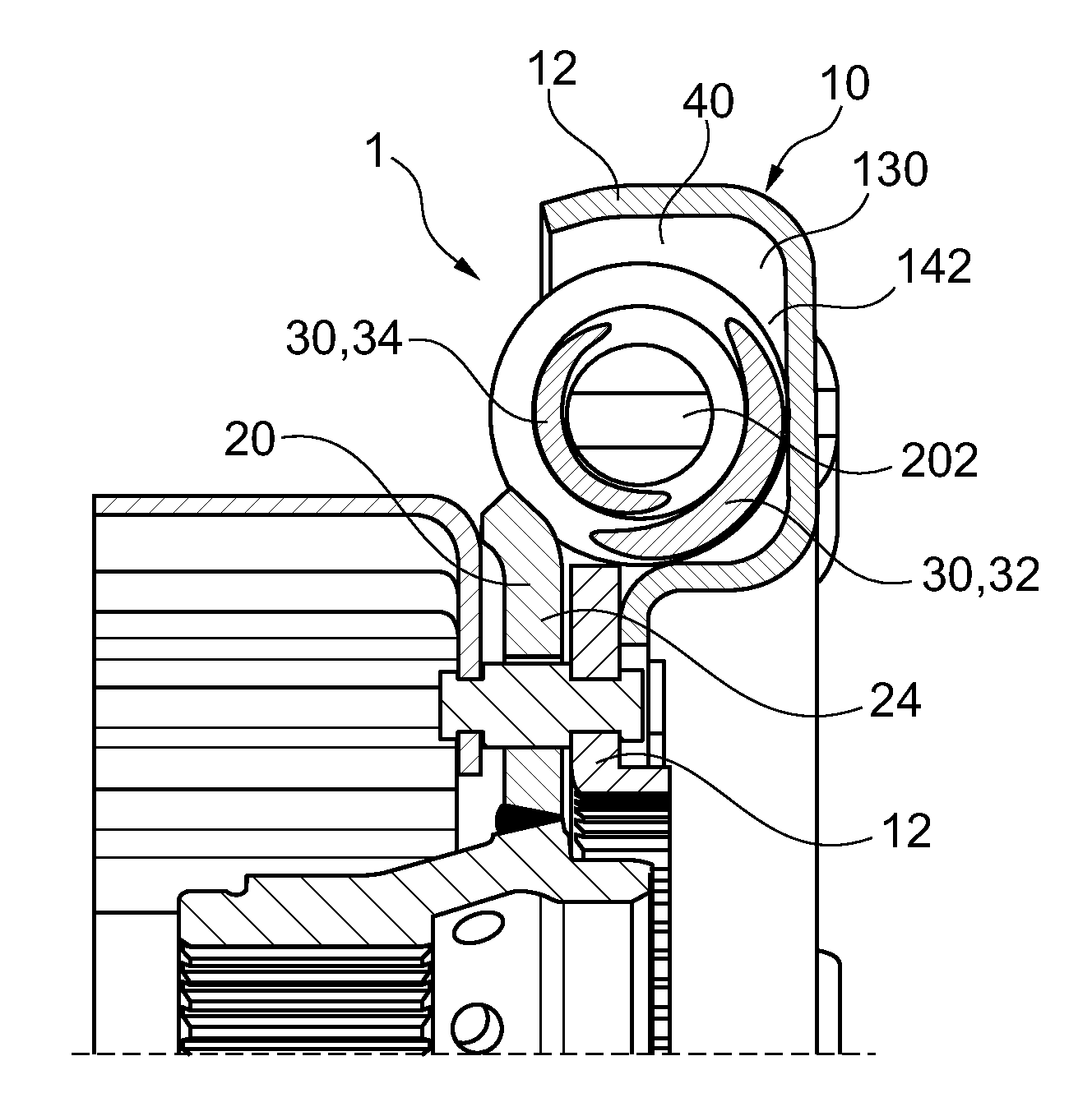
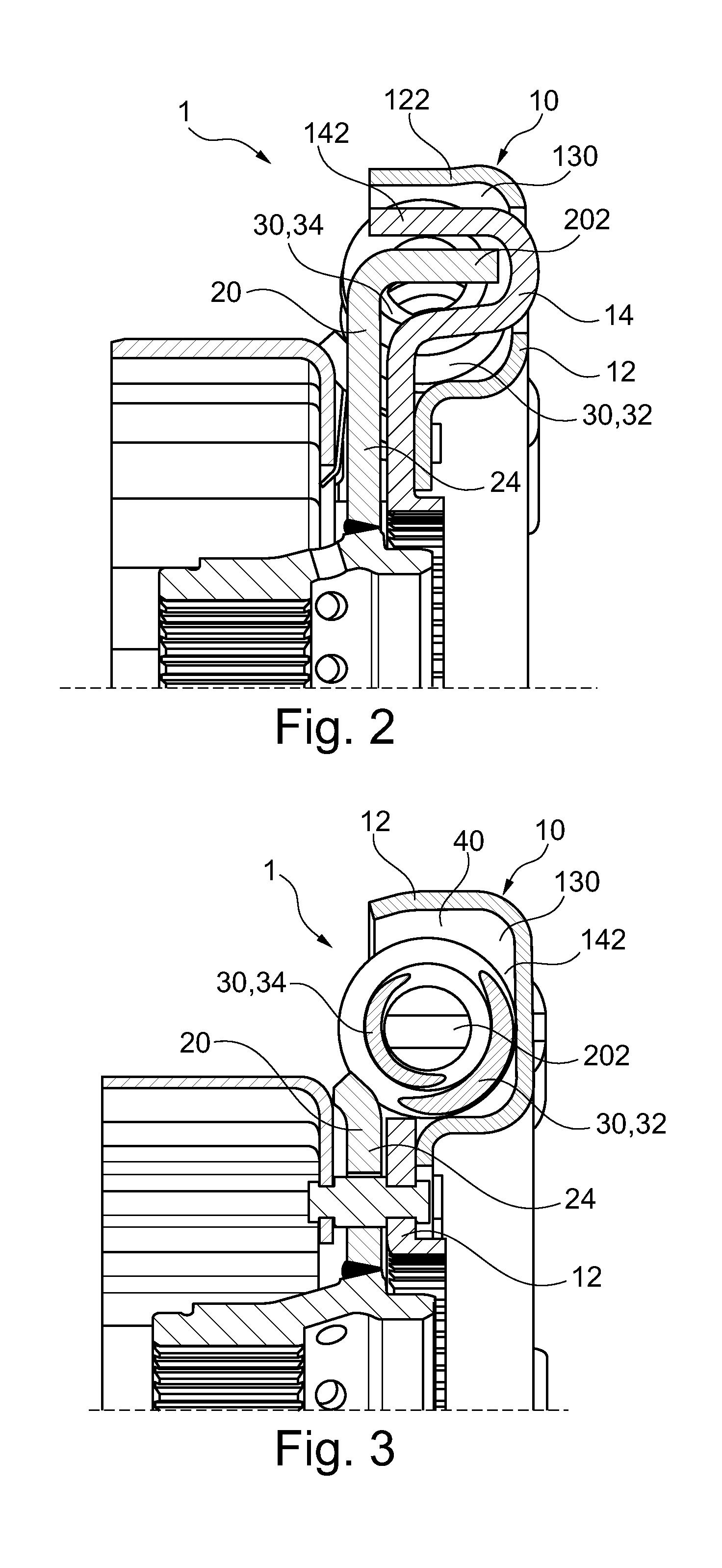
[0030]FIGS. 8 through 17 illustrate the invention, wherein the torsion vibration damper 1 according to the invention includes three bow compression springs 30 or bow compression spring arrangement 30, subsequently designated as bow springs 30, respectively including an outer spring 32 and an inner spring 34. Certainly, in turn, individual springs or single stage or multi stage parallel springs are useable in a different number. The bow springs 30 are received in a spring support housing 12 of a spring support 10 wherein the spring support housing 12 includes an approximately u-shaped ring channel 130 for this purpose (cf. FIGS. 8 and 9). Thus, the longitudinal extensions of the bow springs 30 are received in the circular ring channel 130. (cf. in particular FIG. 14) wherein the bow springs 30 are at least partially supported in axial and radial directions. With the spring support housing 12 a support device 14 is provided which is, in particular, configured as a support ring 14 wher...

third embodiment

[0037]FIGS. 18 through 20 illustrate the third embodiment like a flange hook 202 of the force transmission flange 20, the compression spring 30, thus a straight compression spring 30 (first variant of the invention) or a curved compression spring 30 (bow spring 30, second variant of the invention, wherein only one bow spring is also illustrated in FIGS. 21 through 41 and the following also applies to embodiments of the first variant) and an actuation hook 142 of the spring support 10 or of the support device 14 can interact. The flange hook 202 and the actuation hook 142 are configured analogous to FIG. 1, wherein the flange hook 202 can horizontally reach over a comparatively broad nose at the end cap 36 of the compression spring 30 which prevents a movement of the respective longitudinal end of the compression spring 30 in a radially outward direction. Thus the flange hook 202 reaches over the nose at the end cap 36 in a radial direction partially in a form locking manner. When th...

fifth embodiment

[0039]Furthermore, FIGS. 23 and 24 illustrate the invention wherein the flange hook 202 and the actuation hook 142 are configured analogous to FIG. 1. For radially catching the compression spring 30, the flange hook 202 includes a protrusion 203 extending there from a circumferential and / or tangential direction, or an integrally formed lug which can engage the compression spring 30, in particular, the inner spring 34. Thus the shape of the protrusion 203 is partially configured form locking with an inner contour of the inner spring 34. Lateral edges adjacent to the protrusion 230 when catching the compression spring 30 engage preferably axially opposite portions at the cross section of the outer spring 32 and inner spring 34. An end cap 36 can be omitted in this embodiment.

[0040]FIGS. 25 and 26 represent the sixth embodiment of the invention, wherein the flange hook 202 and the actuation hook 142 are configured analogous to FIGS. 21 and 22. Contrary to the embodiment illustrated in ...


PUM


Abstract

A torsion vibration damper for a drive train of a motor vehicle, in particular a drive train of a hybrid vehicle, comprising: a spring support and a force transmission flange configured rotatable relative to the spring support, wherein at least one compression spring is provided between the spring support and the force transmission flange for transferring a mechanical torque, wherein a housing of the spring support is configured so that in a radial direction of the torsion vibration damper, at least one longitudinal end of the compression spring is supported at/in the spring support housing and/or a clearance remains between windings of a center section of the compression spring and a wall of the spring support.

Description

CROSS-REFERENCE TO RELATED APPLICATIONS[0001]This patent claims priority from German Patent Application No. 10 2011 009 254.4, filed Jan. 24, 2011, which application is incorporated herein by reference in its entirety.FIELD OF THE INVENTION[0002]The present invention relates to a torsion vibration damper for a drive train of a motor vehicle, in particular a drive train of a hybrid vehicle. Furthermore the invention relates to a damping device or a torque transmission device, e.g., a torque converter, a clutch, a clutch assembly, a damper, a torsion vibration damper, a turbine damper, a pump damper, a dual mass converter or a dual mass fly wheel or combinations thereof, optionally with a centrifugal force pendulum, wherein the damping device or the torque transmission device includes a torsion vibration damper.BACKGROUND OF THE INVENTION[0003]In torsion vibration dampers with straight compression springs the compression springs are radially and axially supported by two side discs con...

Claims


Application Information

Patent Timeline
IPC IPC(8): F16F15/123
CPCY02T10/6204F16F15/134F16F15/123F16F15/12326F16F15/1234
Inventor WAHL, PETERSCHENCK, KAI SEBASTIAN
Owner SCHAEFFLER TECH AG & CO KG
Why Eureka
Try Eureka