Power tool

a technology of power tools and motors, applied in the field of power tools, can solve the problems of deteriorating workability and inability to control the rotation number, and achieve the effects of high efficiency, high accuracy and control of the rotation of the motor

Inactive Publication Date: 2012-07-26
HITACHI KOKI CO LTD
View PDF6 Cites 49 Cited by
  • Summary
  • Abstract
  • Description
  • Claims
  • Application Information

AI Technical Summary

Benefits of technology

[0016]According to a fourth aspect of the invention, the target rotation number is so set as to be increased or decreased in proportion to the power supply voltage. Therefore, it is possible to appropriately change the target rotation number, even though the power supply voltage varies.
[0017]According to a fifth aspect of the invention, the control part controls the PWM duty which is supplied to the inverter circuit, thereby to control the rotation of the motor. Therefore, it is possible to control the rotation of the motor with high efficiency and high accuracy.
[0018]According to a sixth aspect of the invention, the control part controls the PWM duty by the PID control, whereby constant-speed control is performed so that the rotation number of the motor may reach the target rotation number, and accurate control of the rotation of the motor can be performed. Moreover, even in case where the rotation of the motor is disturbed due to variation of the load, it is possible to instantly recover the target rotation numb...

Problems solved by technology

For this reason, there occurs such inconvenience that it becomes impossible to control the rotatio...

Method used


Image

  • Power tool
  • Power tool
  • Power tool

Examples


embodiment 1

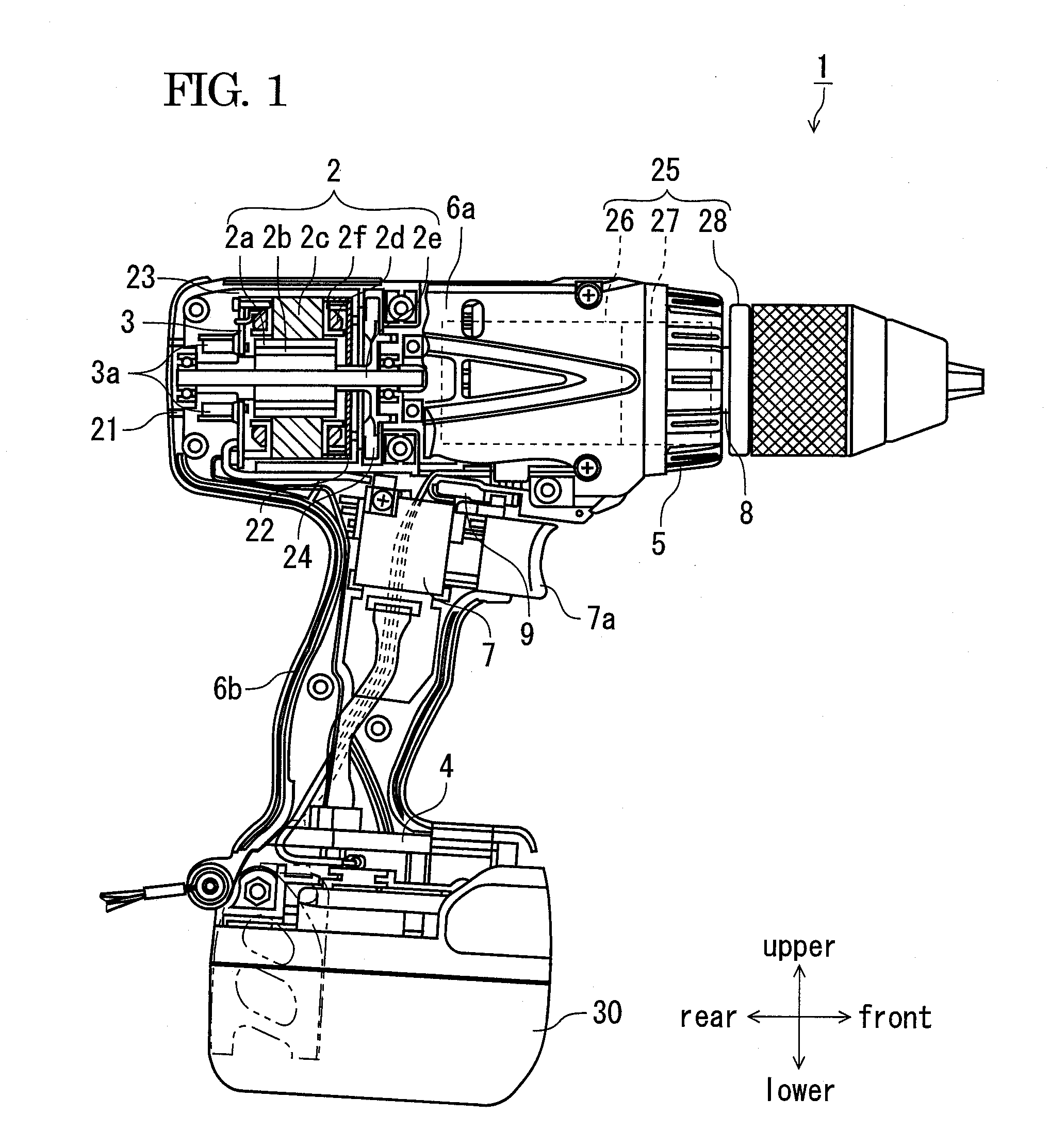
[0038]Now, an embodiment will be described in detail, referring to the drawings. In this specification, upper, lower, front and rear directions respectively correspond to those directions as shown in FIG. 1. FIG. 1 illustrates a power tool according to an embodiment, a part of which being shown in section. Although a driver drill 1 is exemplified in this embodiment, the invention is not limited thereto, and may be applicable to other power tools such as an impact driver, a hammer drill.

[0039]In FIG. 1, a driver drill 1 includes a motor 2 in a barrel housing part 6a, and rotates a tip tool (not shown) such as a driver and a drill to be detachably attached to a chuck 28 mounted on a spindle (an output shaft) 8, through a power transmitting part 25 for transmitting a driving power of the motor 2. An inverter circuit part (a circuit board) 3 for driving the motor 2 is housed in a rear part of the barrel housing part 6a. The barrel housing 6a houses, in an intermediate part and at a fron...

embodiment 2

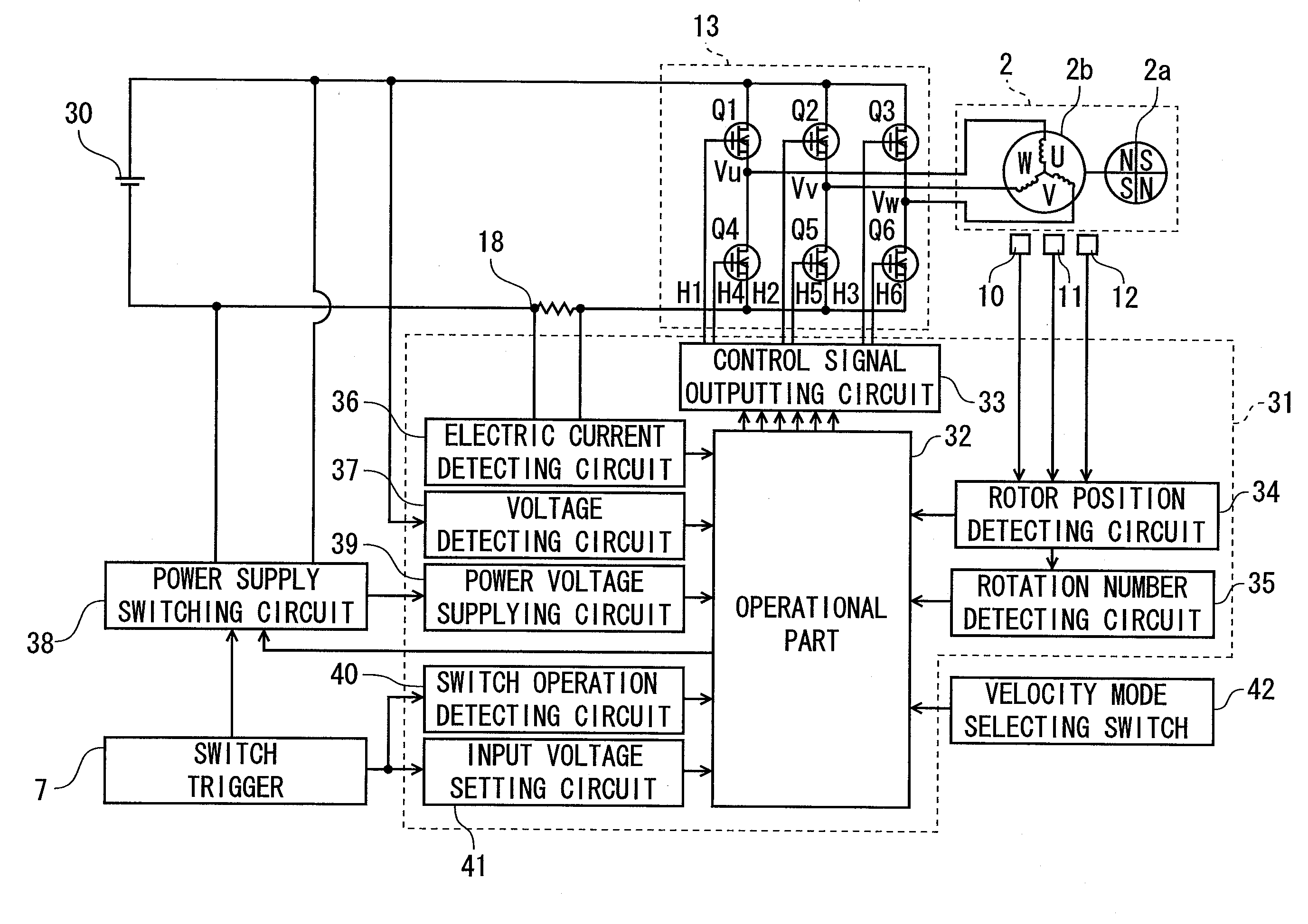
[0067]Referring to FIGS. 9 and 10, a control process flow for the motor in a second embodiment will be described. In the first embodiment, the target rotation number based on the power supply voltage is set every time the switch trigger 7 is pulled. On the other hand, in the second embodiment, the target speed is reset, by measuring the power supply voltage when the velocity mode selecting switch 42 is switched, without performing frequent changes of the target rotation number. The controlling state is shown in FIG. 9. In FIG. 9, a Y-axis represents the power supply voltage (the voltage of the battery pack 30) and the target rotation number (rpm) of the motor 2, and an X-axis represents the time (sec). In a lower part of FIG. 9, operation state of the switch trigger 7 (an output of the switch operation detecting circuit 40) and output signals of the velocity mode selecting switch 42 are also shown correspondingly.

[0068]In FIG. 9, in case where plural works are performed by pulling t...

embodiment 3

[0073]Then, referring to FIGS. 11 to 13, a third embodiment will be described. FIG. 11 illustrates relation between the target rotation number of the motor and the output torque. In the comparison-example method for controlling the rotation of the motor with the PWM duty fixed, when the electric current flowing to the motor is increased due to an increase of load such as a repulsive force from the tip tool, the rotation number of the motor is decreased in inverse proportion to the current, as indicated by a dotted line 111. On the other hand, in a constant-speed control method employing the PID control as indicated n by a solid line 113, for the purpose of rotating the motor at the target speed, the control of the input value is performed by feeding back using three elements including a deviation between the output value and the target value, and an integral and a differential thereof. By using the PID control in this manner, the rotation number of the motor is kept constant, until ...


PUM


Abstract

According to an aspect of the present invention, there is provided a power tool including: a motor; a driving circuit that supplies an electric power from a power supply to the motor; a control part that sets a target rotation number for the motor in accordance with a mode selected from a plurality of modes, each mode having a corresponding target rotation number; and a voltage detecting circuit that detects a voltage of the power supply, wherein the target rotation number is varied based on the detected voltage.

Description

TECHNICAL FIELD[0001]An aspect of the present invention relates a power tool in which the rotation of a motor is controlled.BACKGROUND ART[0002]In a screw fastening power tool such as a driver drill, a given rotation number is previously selected from plural available rotation numbers of a motor, and the screw fastening work is performed by rotating the motor at the selected rotation number. For example, JP-H09-065675-A discloses method for controlling the motor. The rotation number may be selected, for example, by rotating a mode selecting dial, or by pressing a tact switch, at given times. By enabling plural rotation numbers of the motor to be selected, it is possible to efficiently perform extensive works from a low loaded work to a high loaded work. When performing the screw fastening work or the like, it is important to cause the motor to follow the user's operation of a trigger, and to not cause interruption of the motor during the work, from start of the trigger operation unt...

Claims


Application Information

Patent Timeline
IPC IPC(8): G05B13/00
CPCH02P6/06B25F5/00
Inventor IWATA, KAZUTAKATAKANO, NOBUHIROTANIMOTO, HIDEYUKISHIMA, YUKIHIRO
Owner HITACHI KOKI CO LTD
Why Eureka
Try Eureka