Computer system and method for signal transmitting

a computer system and signal transmission technology, applied in the direction of instruments, electric digital data processing, etc., can solve the problems of affecting the so as to prevent the erroneous operation of the pcie componen

Inactive Publication Date: 2012-07-26
HITACHI LTD
View PDF2 Cites 26 Cited by
  • Summary
  • Abstract
  • Description
  • Claims
  • Application Information

AI Technical Summary

Benefits of technology

[0020]When the relay buffer is used to transmit a signal for a long distance out of the PCIe specification, the substitute signal is transmitted without turning into the EI state, thus making it possible to inhibit the occurrence of the random pattern signal and prevent erroneous operation of the PCIe component.

Problems solved by technology

However, the transmission of electrical signals using a wiring or a cable on a printed board has a problem that transmission distance is limited, because signal attenuation rate increases as signal frequency increases due to a so-called skin effect.
If the length of the wiring is longer than that defined in the PCIe interface specification due to board design constraint or the like, an input signal of the PCIe interface which has been inputted to the relay buffer of the PCIe interface is greatly attenuated and sometimes falls below the threshold value set to the relay buffer, resulting in a normal signal being filtered as noise.
On the other hand , when the relay buffer does not perform filtering and amplifies the whole inputted signals, the relay buffer amplifies even the noise.
However, typically, since commercially available relay buffers are set with the threshold value defined in the PCIe interface specification, it then becomes impossible to use the commercially available components, requiring the development of parts.
It then also becomes necessary to make development cost for a device undesirably increased.
In the LSI that received the random pattern signal, an internal logic circuit likely causes an unexpected operation, when it receives an input that has not been defined by the PCIe interface specification.
In the case of conventional single route connection, if an I / O device works erroneously, the trouble has an impact only on the interior of a PCI tree that constitutes a PCI device connected to a processing module.
However, in the case of a multiple connection in which a plurality of processing modules share the I / O device via a switch, if the PCIe switch malfunctions, each PCI tree connected is influenced, and an operation of the entire system may be suspended.
The EI state also raises another problem when an optical cable is used for PCIe communications.
Such electrical potential difference may be detected as 1 / 0 of data resulting in the possibility that irregular pattern signals will be outputted.

Method used


Image

  • Computer system and method for signal transmitting
  • Computer system and method for signal transmitting
  • Computer system and method for signal transmitting

Examples


embodiment 1

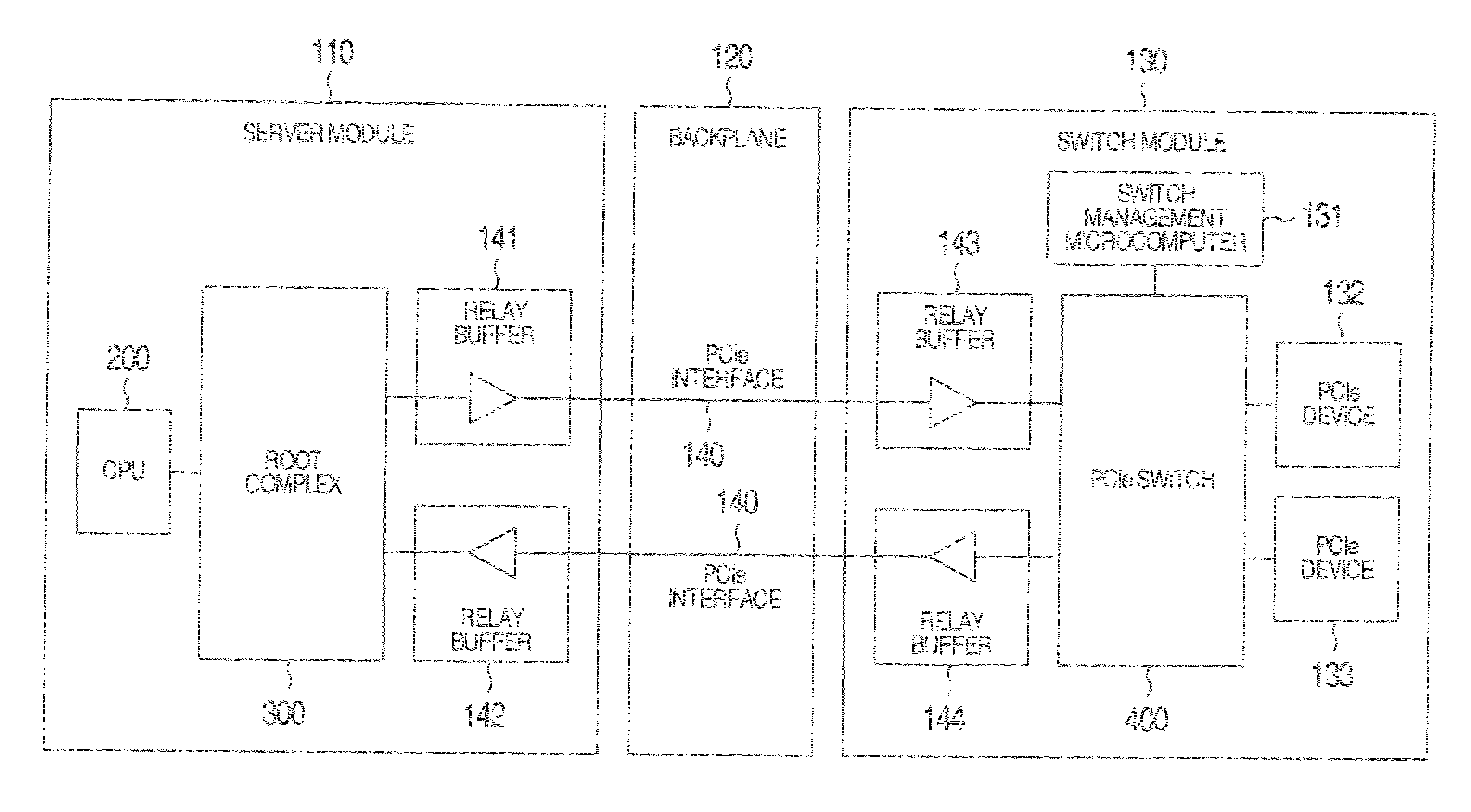
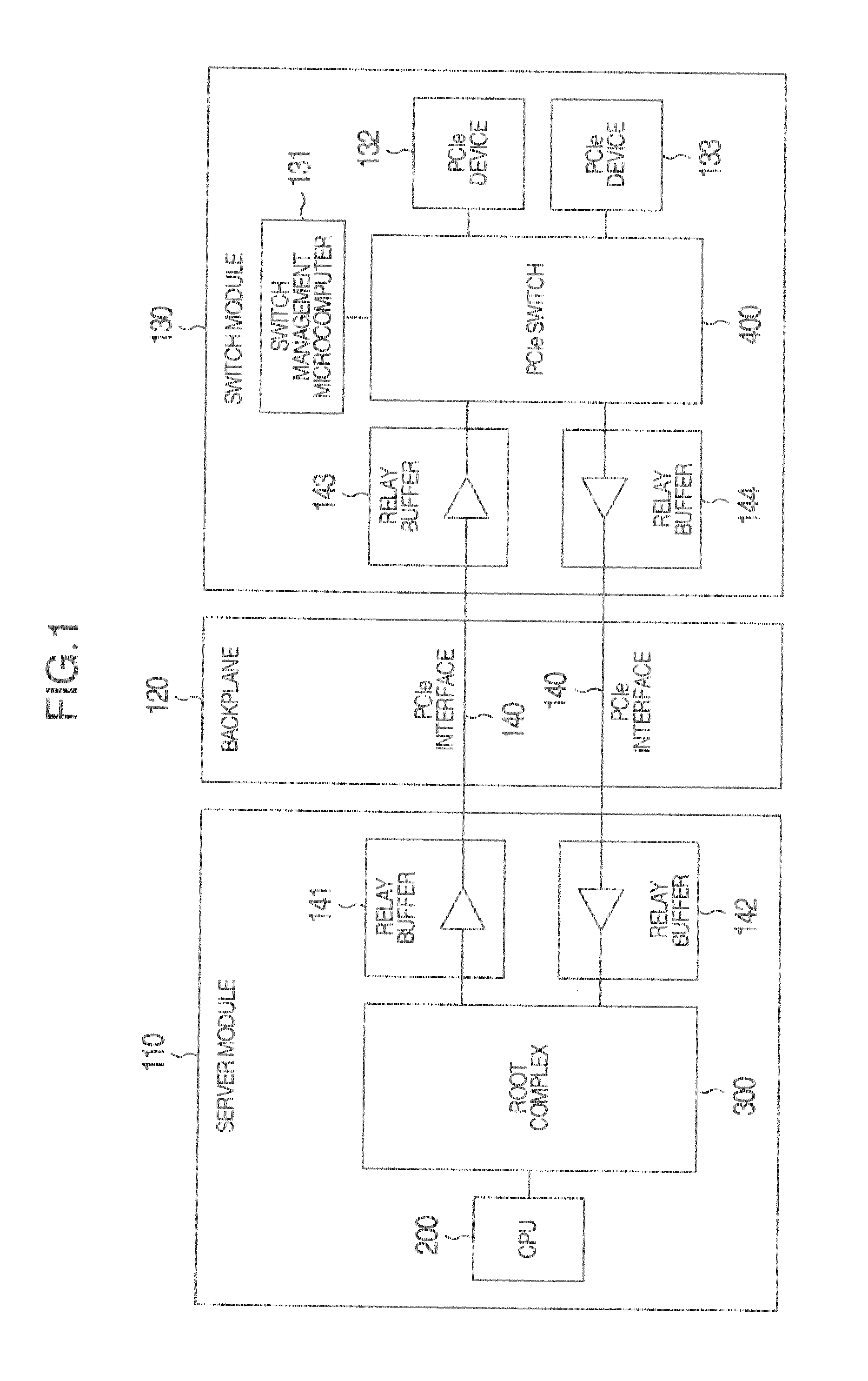
[0032]The structure of a computer system according to Embodiment 1 to which the present invention is applied will be described with reference to FIG. 1. The server device includes a server module 110 and a switch module 130, with the server module 110 being connected to the switch module 130 via a backplane 120,

[0033]The server module 110 has a CPU 200 and a root complex 300, with the root complex 300 being connected to a PCIe switch 400 mounted on the switch module 130 via PCIe interfaces 140, Relay buffers 141, 142 on the server module 110 and relay buffers 143, 144 on the switch module 130 is connected to the PCIe interfaces 140. These relay buffers have an equalizer function and a pre-emphasis function, and compensate waveform of a signal.

[0034]The switch module 130 has the PCIe switch 400, a switch management microcomputer 131, and one or more PCIe devices 132, 133. The switch management microcomputer 131 manages setting operations of the PCIe switch 400.

[0035]Next, a connectio...

embodiment 2

[0101]In Embodiment 2, an optical cable 150 is employed to connect between the server module 110 and the switch module 130 instead of the backplane 120 which is used in Embodiment 1.

[0102]A computer system according to Embodiment 2 of the present invention will be described with reference to FIG. 9.

[0103]The computer system has a server module 110 and a switch module 130. The server module 110 is connected to the switch module 130 via electrical / optical conversion units 161, 164, optical / electrical conversion units 162, 163 and an optical cable 150. Other constructions are the same as those in Embodiment 1.

[0104]In the transmission of the PCIe signal over an optical cable, the PCIe port in a normal mode cannot perform normal operation in transmission. Therefore, the mode in which EI is not used is always employed for transmission.

[0105]As described in the above, the PCIe signal can be transmitted over an optical cable which operates in normal operations and the optical cable can tra...


PUM


Abstract

In order to suppress occurrence of a random pattern signal is suppressed without the use of a sideband signal in a long distance data transmission exceeding that defined in a PCIe interface specification, provided is a computer system, including a first component having a transmitting unit which transmits a control signal, a second component having a receiving unit which receives the control signal, a transmission path which connects the first component and the second component along which a signal is transmitted and received, wherein: in case of the transmitting unit of the first component transmits a ternary signal with three states of 0/1/Idle to the receiving unit of the second component, the transmitting unit of the first component substitutes a combination of signals representing 0/1 for a signal representing the Idle state, and transmits the substituted signals instead of the ternary signal to the receiving unit of the second component.

Description

BACKGROUND OF THE INVENTION[0001]The present invention relates to a computer system having a PCI Express interface and signal transmitting method. More particularly, the present invention relates to both a computer system in which transmission distance of the PCI Express interface can be made extendable and a signal transmitting method therefor.[0002]Conventionally, in the computer system, a Peripheral Component Interconnect Express (PCIe) has been widely employed (such as shown in PCI Express Base Specification Revision 2.0 (chapter 1 and chapter 4)). In the PCIe, the number of I / O devices connectable to a processing module can be increased by disposing a switch within the construction. Also in a Multi-Root I / O Virtualization (MR-IOV), which is an extended specification for the PCIe, a plurality of such processing modules can share the common FP device through the intermediary of a MR-IOV-compliant switch. In order to extend the I / O device in a processing module which structurally ...

Claims


Application Information

Patent Timeline
Patent Type & Authority Applications(United States)
IPC IPC(8): G06F13/42
CPCG06F2213/0026G06F13/4282
Inventor YAMAUCHI, TATSUYAKOBAYASHI, MASAHIROYAMAGATA, RYOTAMURA, TAKASHIWATANABE, KENICHI
Owner HITACHI LTD
Why Eureka
Try Eureka