Vacuum heating/cooling apparatus and manufacturing method of magnetoresistance element

a technology of magnetoresistance element and vacuum heating/cooling apparatus, which is applied in the direction of lighting and heating apparatus, drying machines, furnaces, etc., can solve the problems of large exposure time t, poor vacuum degree, and loss of transfer tim

Active Publication Date: 2012-08-02
CANON ANELVA CORP
View PDF20 Cites 35 Cited by
  • Summary
  • Abstract
  • Description
  • Claims
  • Application Information

AI Technical Summary

Benefits of technology

[0044]According to the present invention, even after the film formation processing, only the substrate can be rapidly heated or rapidly cooled while a high vacuum degree is maintained.

Problems solved by technology

In the prior-art methods in which the substrate is transferred to another chamber for cooling, there is a problem in which time required for transfer is lost, that is, the exposure time T becomes large.
The method of cooling the substrate by introducing cooling gas into the heating chamber has a problem in which the vacuum degree gets poor, that is, the pressure P is raised.
In the method of heating and cooling the substrate supporting base itself, there is a problem in which temperature rise and temperature drop speeds become slow for the heat capacity of the substrate supporting base, and particularly when the substrate temperature is to be lowered approximately to a room temperature, it takes a long time and also increases the exposure time T.
In the prior-art method of performing either of heating or cooling processes in the load lock chamber, to conduct the heating or cooling process of a thin film rapidly and continuously is impossible.
Even if the substrate is returned to the load lock chamber after film formation and the heating / cooling process is conducted continuously, film formation cannot be performed subsequently due to an operation sequence of the apparatus.
Also, there is a problem that the PT product is extraordinarily high, since the load lock chamber which is vented to the atmospheric pressure at each processing has a low vacuum degree, that is, high pressure P.
In an apparatus which conducts heating treatment for a large quantity of the substrates in the magnetic field, the substrates to which the film formation treatment has been applied in another film forming apparatus are taken out into the atmosphere once and put into an apparatus for heating in the magnetic field again to perform heating treatment, and thus, the film forming process and the heating / cooling process cannot be conducted in a continuous vacuum.
In the apparatus which applies the magnetic field during film formation, too, the heating / cooling function is not provided, and the heating / cooling processing in a continuous vacuum after the film formation is not possible.

Method used


Image

  • Vacuum heating/cooling apparatus and manufacturing method of magnetoresistance element
  • Vacuum heating/cooling apparatus and manufacturing method of magnetoresistance element
  • Vacuum heating/cooling apparatus and manufacturing method of magnetoresistance element

Examples


first embodiment

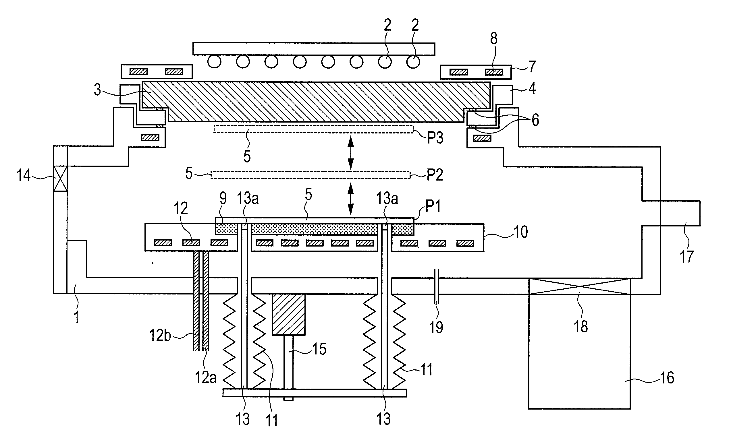
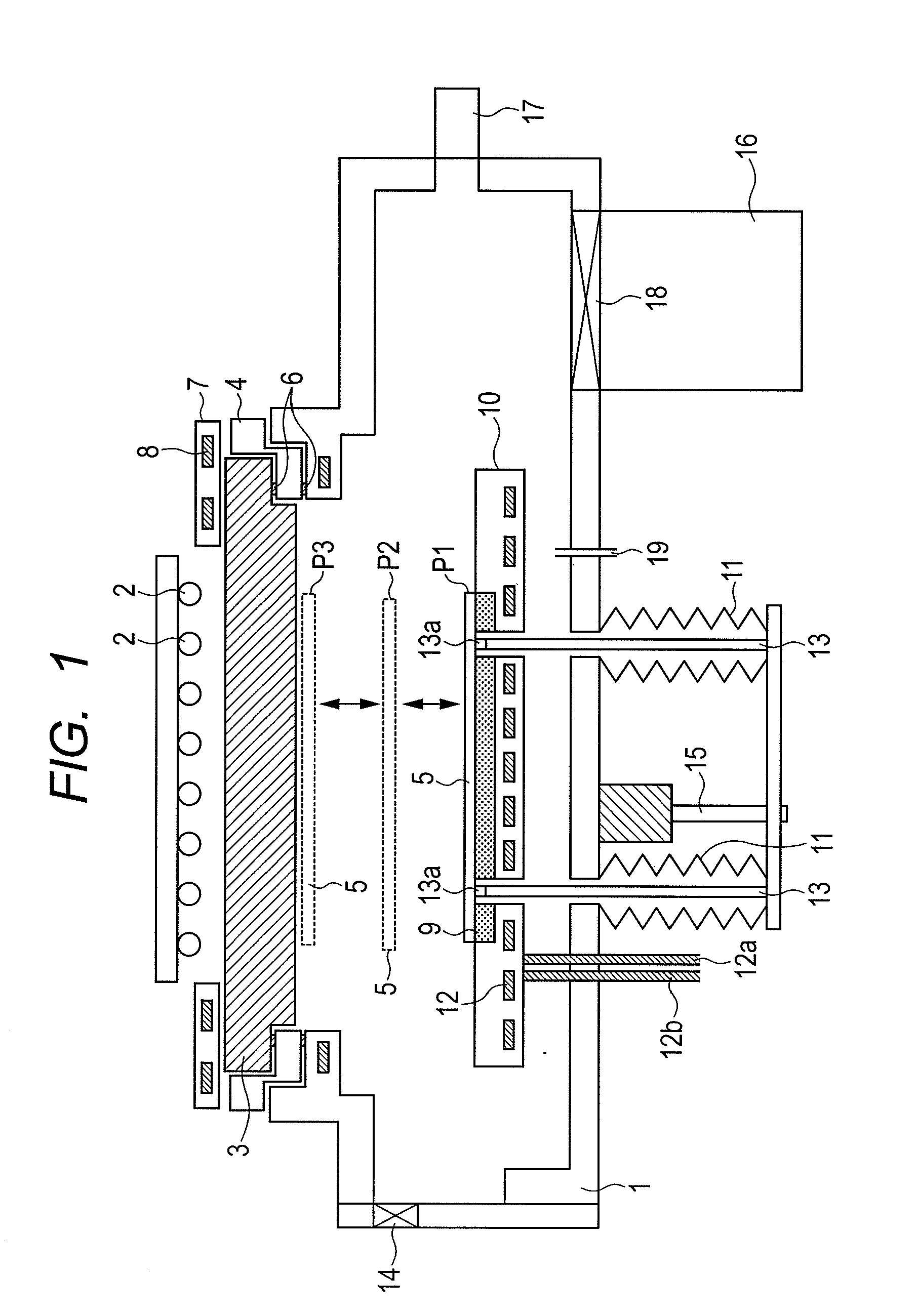
[0060]FIG. 1 is an apparatus configuration diagram of a vacuum heating / cooling apparatus according to this embodiment.

[0061]In FIG. 1, on an upper part of a vacuum chamber 1, a quartz window 3 which transmits heating light from a halogen lamp 2 is fixed through a vacuum seal member (not shown). This quartz window 3 functions as an incident portion for causing the heating light output from the halogen lamp 2 to enter the vacuum chamber 1. The vacuum seal member preferably has high heat resistance such as Viton (registered trademark) or Kalrez (registered trademark). By providing a ring 4 for attaching / detaching the quartz window between the vacuum chamber 1 and the quartz window 3 as illustrated in FIG. 1, attachment / detachment of the quartz window 3 is facilitated. The size of the quartz window 3 is preferably 1.5 times or more the size of a substrate 5. Also, the halogen lamp 2 as a radiation energy source which radiates the heating light is arranged on the atmosphere side. That is...

second embodiment

[0097]In the first embodiment, if the heating temperature is high or depending on the type of the substrate 5, when the substrate 5 is placed on the cooled substrate supporting base 9, the substrate might be split by thermal shock. In order to prevent such split of the substrate, in this embodiment, after the heating in the first embodiment is finished, the substrate 5 is not immediately placed on the substrate supporting base 9 when the lift pins 13 are lowered but the substrate is stopped once at a predetermined position above the substrate supporting base 9. Such a predetermined position is preferably within 20 mm above the substrate supporting base 9. Alternatively, during non-heating, the substrate 5 may be stopped once at a position where the distance between the halogen lamp 2 and the substrate 5 is 100 mm or more.

[0098]By configuring above, the substrate can be cooled while split is avoided. That is, in this embodiment, if the temperature of the substrate 5 has fallen to a t...

third embodiment

[0099]In the first and second embodiments, in order to further reduce time till the substrate temperature reaches the room temperature after the substrate 5 is placed on the cooled substrate supporting base 9, at least one of provision of an electrostatic adsorption mechanism such as an electrostatic chuck on the substrate supporting base 9 and supply of cooling gas to the surface of the substrate supporting base 9 is effective.

[0100]FIG. 4 is a diagram for explaining a mode in which an electrostatic chuck function is provided in the substrate supporting base of the vacuum heating / cooling apparatus illustrated in FIG. 1.

[0101]In FIG. 4, a substrate supporting base 41 is one adding the electrostatic chuck function to the substrate supporting base 9 illustrated in FIG. 1 according to this embodiment. Specifically, the substrate supporting base 41 made of a dielectric body is in contact with or incorporates wiring (not shown) which introduces electricity (electric power), and the wirin...


PUM


Abstract

The present invention provides a vacuum heating / cooling apparatus capable of rapidly heating and also rapidly cooling only a substrate while a high vacuum degree is maintained after film-formation processing. The vacuum heating / cooling apparatus according to an embodiment of the present invention includes a vacuum chamber (1), a halogen lamp (2) which emits heating light, a quartz window (3) for allowing the heating light to enter the vacuum chamber (1), a substrate supporting base (9) having a cooling function, and a lift pin (13) which causes the substrate (5) to stand still at a heating position P3 and a cooling position P1 and moves the substrate (5) between the heating position P3 and the cooling position P1.

Description

CROSS-REFERENCES TO RELATED APPLICATIONS[0001]This application is a continuation application of International Application No. PCT / JP2010 / 056855, filed Apr. 16, 2010, which claims the benefit of Japanese Patent Application No. 2009-150055, filed Jun. 24, 2009. The contents of the aforementioned applications are incorporated herein by reference in their entities.TECHNICAL FIELD[0002]The present invention relates to a vacuum heating / cooling apparatus which heats / cools a substrate of a semiconductor device, an electronic device, a magnetic device, a display device and the like in vacuum at a high speed and to a manufacturing method of a magnetoresistance element.BACKGROUND ART[0003]A tunnel magnetoresistance element having an MgO tunnel barrier layer used as a sensor element of a magnetic random access memory (MRAM) or a magnetic head forms a structure in which a metal film (a magnetic film and a nonmagnetic film) and an insulator film are laminated in multiple layers. Such a magnetores...

Claims


Application Information

Patent Timeline
Patent Type & Authority Applications(United States)
IPC IPC(8): H01L21/477F27D11/12F25B29/00
CPCH01L21/67109H01L43/12H01L21/6719H01L21/67115H10N50/01H01L21/26H01L21/67196H01L21/324
Inventor TSUNEKAWA, KOJINAGAMINE, YOSHINORIFURUKAWA, SHINJI
Owner CANON ANELVA CORP
Why Eureka
Try Eureka