Method of manufacturing a glass substrate for a magnetic disk and method of manufacturing a magnetic disk

a glass substrate and magnetic disk technology, applied in the field of manufacturing a glass substrate for a magnetic disk and a manufacturing method of a magnetic disk, can solve the problems of increasing the possibility of collision with the magnetic head, increasing the roughness, and increasing the error rate of reading or writing a magnetic signal, so as to achieve less surface defects, high polishing rate, and low cost

Active Publication Date: 2012-08-02
HOYA CORP
View PDF9 Cites 10 Cited by
  • Summary
  • Abstract
  • Description
  • Claims
  • Application Information

AI Technical Summary

Benefits of technology

[0035]According to this invention, while maintaining the high polishing rate, it is possible to manufacture, at a low cost, a high-quality magnetic disk glass substrate with less surface defects such as scratches than a conventional product. The magnetic disk glass substrate obtained by this invention can be suitably used particularly as a next-generation substrate of wh

Problems solved by technology

Under these circumstances, if an extremely small surface defect such as a scratch, which did not arise as a problem conventionally, is present on a substrate surface while the average roughness of the substrate surface is extremely small, both sides of the scratch of the substrate surface may rise even on the medium surface, and therefore, the possibility of collision with the magnetic head increases.
Further, since the distance between the magnetic layer of the medium and the element portion of the magnetic head becomes large at a bottom (valley) portion of the scratch, error tends to occur in reading or writing a magneti

Method used


Image

  • Method of manufacturing a glass substrate for a magnetic disk and method of manufacturing a magnetic disk
  • Method of manufacturing a glass substrate for a magnetic disk and method of manufacturing a magnetic disk
  • Method of manufacturing a glass substrate for a magnetic disk and method of manufacturing a magnetic disk

Examples


example 1

[0083]A magnetic disk glass substrate of this Example was manufactured through (1) Rough Lapping Process (Rough Grinding Process), (2) Shaping Process, (3) Precision Lapping Process (Precision Grinding Process), (4) End Face Polishing Process, (5) Main Surface First Polishing Process, (6) Chemical Strengthening Process, and (7) Main Surface Second Polishing Process, which will be described hereinbelow.

[0084](1) Rough Lapping Process

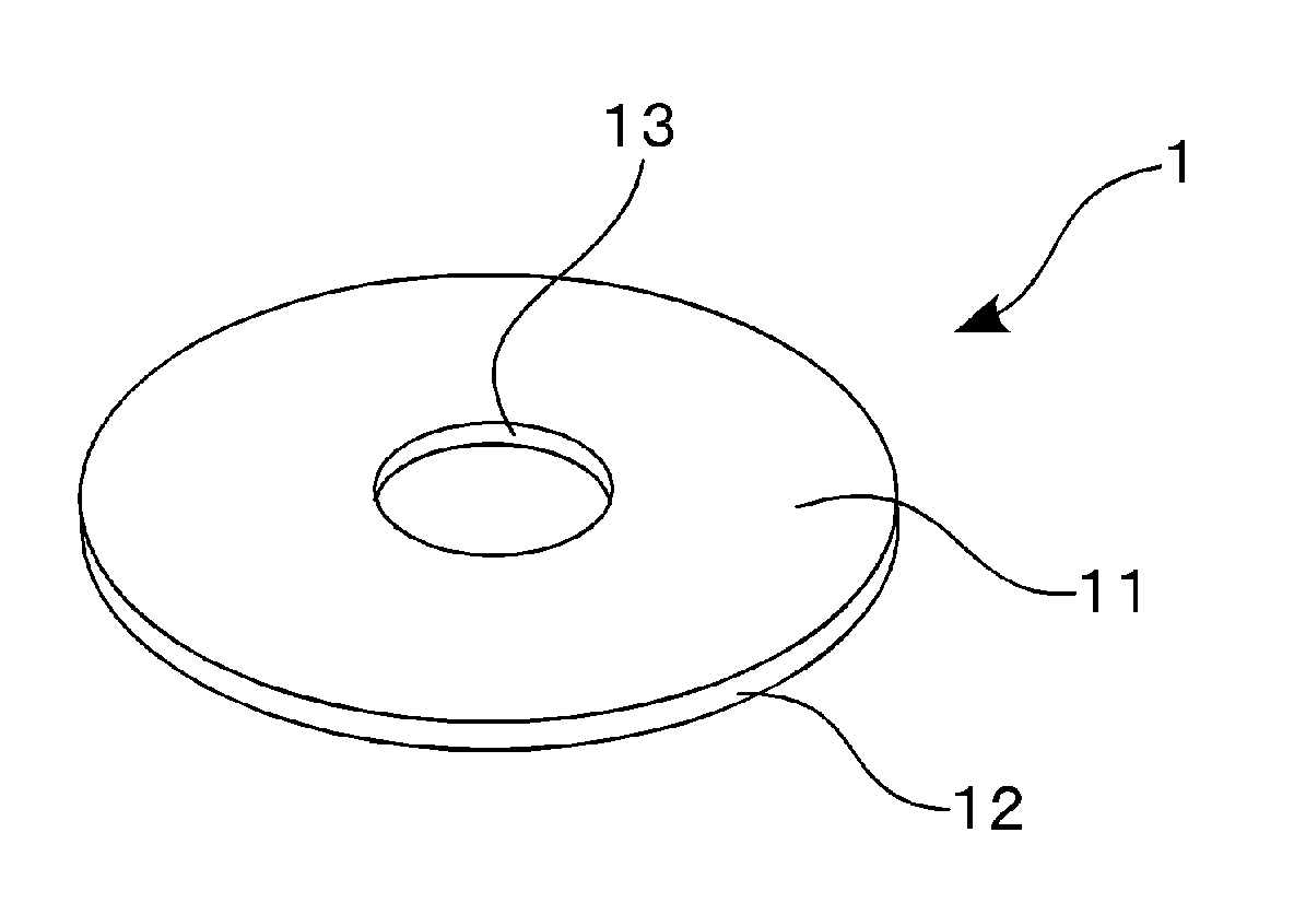
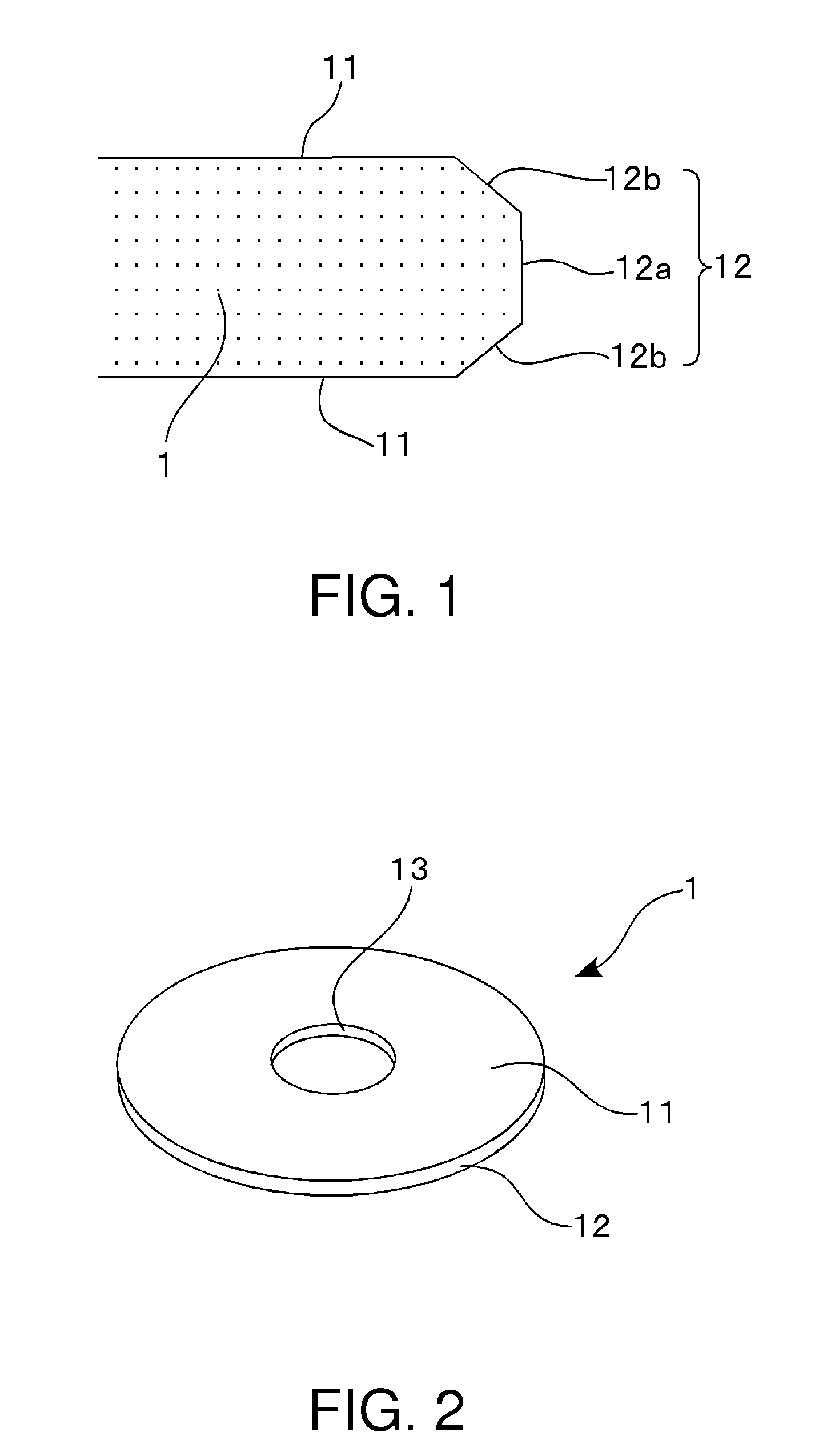
[0085]First, a disk-shaped glass substrate made of an aluminosilicate glass and having a diameter of 66 mm and a thickness of 1.0 mm was obtained from a molten glass by direct pressing using upper, lower, and drum molds. Alternatively, a plate glass may be manufactured by a downdraw method or a float method and then cut into a disk-shaped glass substrate with a predetermined size. As the aluminosilicate glass, use was made of a glass for chemical strengthening containing 58 wt % to 75 wt % SiO2, 5 wt % to 23 wt % Al2O3, 3 wt % to 10 wt % Li2O, and 4 wt % ...

example 2

[0107]The second polishing process was carried out in the same manner as in Example 1 except that the friction coefficient between each polishing pad and the glass substrate was adjusted to 0.038 using a polishing liquid added with 0.1 wt % Aron A-6016A. Magnetic disk glass substrates were obtained in the same manner as in Example 1 except for this second polishing process.

[0108]The surface roughness of main surfaces of the obtained 100 glass substrates was measured using an atomic force microscope (AFM). As a result, the surface roughness was 0.143 nm in Ra, representing an ultra-smooth surface smoother than a conventional product. Further, a scratch evaluation was carried out in the same manner as in Example 1.

[0109]In Table 1 given later, the above-mentioned Ra value, a scratch evaluation, and a polishing rate value in the above-mentioned second polishing process are shown. According to this Example, while maintaining the high polishing rate, it is possible to further reduce surf...

example 3

[0110]The second polishing process was carried out in the same manner as in Example 1 except that the friction coefficient between each polishing pad and the glass substrate was adjusted to 0.048 using a polishing liquid added with 0.05 wt % Aron A-6016A. Magnetic disk glass substrates were obtained in the same manner as in Example 1 except for this second polishing process.

[0111]The surface roughness of main surfaces of the obtained 100 glass substrates was measured using an atomic force microscope (AFM). As a result, the surface roughness was 0.146 nm in Ra, representing an ultra-smooth surface smoother than a conventional product. Further, a scratch evaluation was carried out in the same manner as in Example 1.

[0112]In Table 1 given later, the above-mentioned Ra value, a scratch evaluation, and a polishing rate value in the above-mentioned second polishing process are shown. According to this Example, while maintaining the high polishing rate, it is possible to further reduce sur...


PUM

PropertyMeasurementUnit
Massaaaaaaaaaa
Speedaaaaaaaaaa
Particle sizeaaaaaaaaaa

Abstract

A method of manufacturing a glass substrate for a magnetic disk includes a polishing step of polishing a main surface of a glass substrate by sandwiching the glass substrate between a pair of surface plates each having a polishing pad on its surface and by supplying a polishing liquid containing polishing abrasive particles between the glass substrate and the polishing pads. In the polishing step, the polishing liquid and each polishing pad are adjusted so that the friction coefficient falls in a range of 0.02 to 0.05.

Description

[0001]This application is based upon and claims the benefit of priority from Japanese patent application No. 2011-014990, filed on Jan. 27, 2011, the disclosure of which is incorporated herein in its entirety by reference.TECHNICAL FIELD[0002]This invention relates to a method of manufacturing a glass substrate for a magnetic disk adapted to be mounted in a magnetic disk device such as a hard disk drive (HDD) and further relates to a method of manufacturing the magnetic disk. Hereinafter, a glass substrate for a magnetic disk may also be referred to as a magnetic disk glass substrate.BACKGROUND ART[0003]As an information recording medium adapted to be mounted in a magnetic disk device such as a hard disk drive (HDD), there is a magnetic disk. The magnetic disk is produced by forming a thin film such as a magnetic layer on a substrate and, conventionally, an aluminum substrate has been used as such a substrate. Recently, however, in response to the pursuit of higher recording density...

Claims


Application Information

Patent Timeline
IPC IPC(8): G11B5/84B24B1/00
CPCB24B7/228B24B37/28G11B5/8404
Inventor SAKAI, HIDEOTAWARA, YOSHIHIRO
Owner HOYA CORP
Why Eureka
Try Eureka