Device and method for directing radiation in the direction of an optical element of an image sensing device of a vehicle

an image sensing device and optical element technology, applied in scene recognition, television systems, instruments, etc., can solve the problems of reducing installation costs, requiring a larger sensor, and a different lens system, so as to achieve low manufacturing and processing costs, flexible use, and improved flexibility

Active Publication Date: 2012-08-09
ROBERT BOSCH GMBH
View PDF6 Cites 1 Cited by
  • Summary
  • Abstract
  • Description
  • Claims
  • Application Information

AI Technical Summary

Benefits of technology

[0019]According to another specific embodiment, the device may have a switchable glass element, the central area and the at least one border area being sections of the switchable glass element, the switchable glass element being designed to switch the central area and the at least one border area between a transparent state and a mirrored state. An exemplary switchable glass element may typically include three components: a transparent substrate, an active switchable metal-hydrogen layer and a top layer, e.g., of palladium, which protects the active layer from oxidation and enables hydrogen dissociation. The active layer may contain, for example, magnesium and 3d transition mixed metal and may be made reversibly transparent through hydrogen absorption or chemical electrolysis, by applying an electrical current to the switchable glass element. Such a specific embodiment of the present invention offers the advantage that the device is usable more flexibly and in a more versatile manner because the central area and the at least one border area are reversibly adjustable in their transparency characteristics.
[0020]The central area and the at least one border area may be designed in the transparent state to guide the first incident radiation to the optical element, and the central area and the at least one border area may be designed in the mirrored state to direct the second incident radiation onto the optical element. Such a specific embodiment of the present invention offers the advantage that the sensing area or the value area for the angles of incidence is enlarged for the first incident radiation as well as for the at least one second incident radiation. Depending on the switching status of the switchable glass element, both the central area and the at least one border area are thus a

Problems solved by technology

However, the resulting extra costs for a different lens system, a larger sensor, an additional algorithm,

Method used


Image

  • Device and method for directing radiation in the direction of an optical element of an image sensing device of a vehicle
  • Device and method for directing radiation in the direction of an optical element of an image sensing device of a vehicle
  • Device and method for directing radiation in the direction of an optical element of an image sensing device of a vehicle

Examples


Embodiment Construction

[0040]In the following description of preferred exemplary embodiments of the present invention, the same or similar reference numerals are used for the elements depicted in the various figures, which also have a similar effect, so these elements will not be described again.

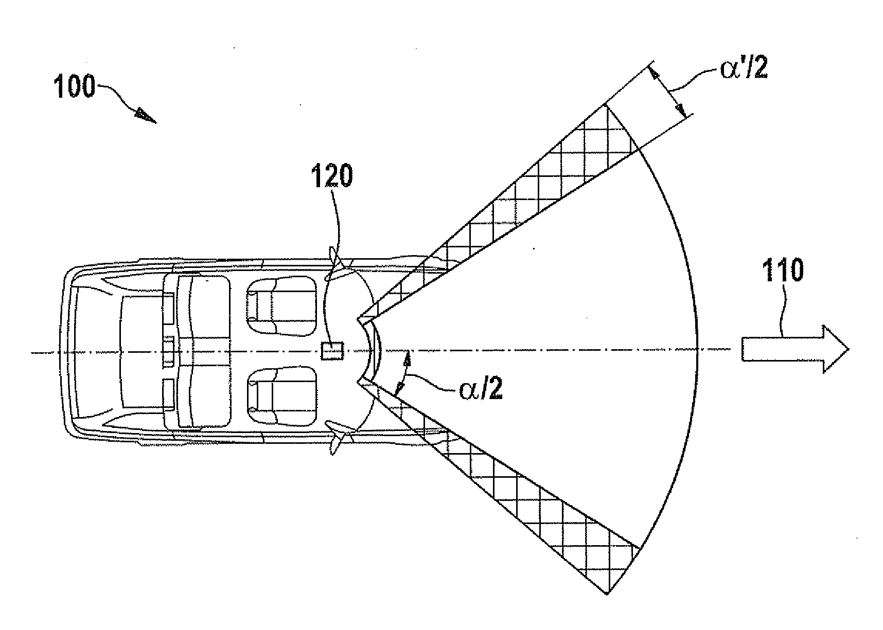
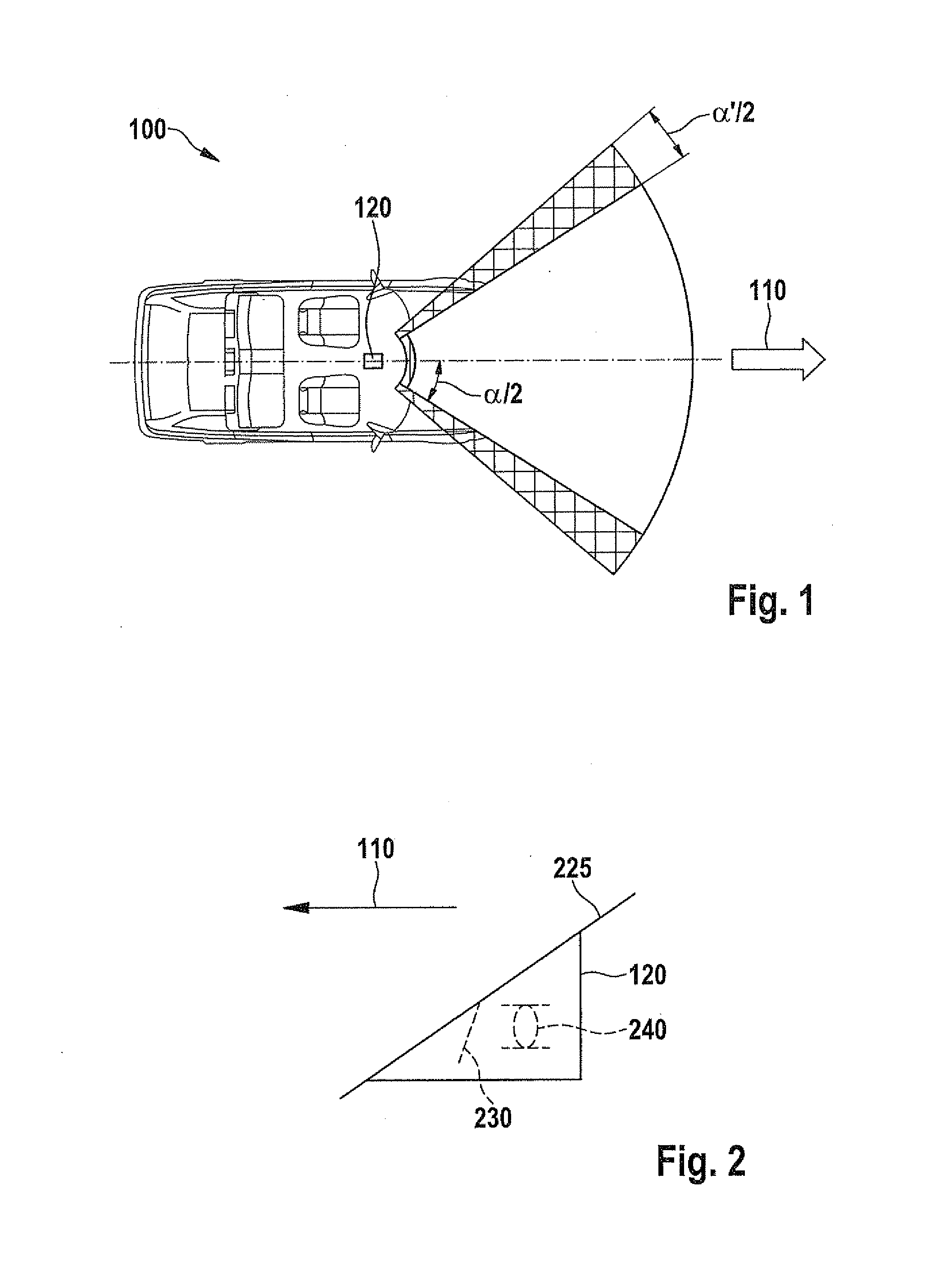
[0041]FIG. 1 shows a schematic top view of a vehicle 100 having an expanded camera sensing range according to one exemplary embodiment of the present invention. This shows a travel direction 110 of vehicle 100, a camera housing 120, a required sensing range for forward-looking functions, spanned by two times angle α / 2 and two adjacent areas which are additionally needed for sensing the interior, each being spanned by angle α′ / 2. Both angles α / 2 proceed from a central longitudinal axis of vehicle 100. Camera housing 120 is situated in the area of the central longitudinal axis of vehicle 100. Camera housing 120 may contain a camera system, for example, a video camera system having a pre-crash sensor. The viewing dir...


PUM


Abstract

A device for directing radiation in the direction of an optical element of an image sensing device of a vehicle. The device includes a central area for directing at least one portion of a first incident radiation onto the optical element. The device also includes at least one border area for directing at least one portion of at least one second incident radiation onto the optical element. The at least one second incident radiation runs in the opposite direction or at an obtuse angle with respect to the first incident radiation.

Description

CROSS REFERENCE[0001]The present application claims the benefit under 35 U.S.C. §119 of German Patent Application no. DE 102011003796.9-51 filed on Feb. 8, 2011, which is expressly incorporated herein by reference in its entirety.[0002]1. Field of the Invention[0003]The present invention relates to a device and a method for directing radiation in the direction of an optical element of an image sensing device of a vehicle and a camera system for detecting a first incident radiation from a direction of the windshield of a vehicle and at least one second incident radiation from a direction of the interior of the vehicle.[0004]2. Background Information[0005]Video camera systems (mono video or stereo video) are used in vehicles for monitoring in the travel direction. Safety systems of the active type, e.g., automatic braking functions, are based mainly on these systems. In addition, video systems may also be provided in vehicles for monitoring the passenger compartment.[0006]German Paten...

Claims


Application Information

Patent Timeline
IPC IPC(8): H04N7/18G02B27/14G02B5/08G06V10/147
CPCG06K9/00805B60R21/01538G06K9/00845G06K9/209G06V20/597G06V20/58G06V10/147
Inventor D'ADDETTA, GIAN ANTONIOLICH, THOMASFRIEDRICH, THOMAS
Owner ROBERT BOSCH GMBH
Why Eureka
Try Eureka