Nanotube-nanohorn complex and method of manufacturing the same

a technology of nanotubes and nanohorns, applied in the field of nanotubes and nanohorn complexes, can solve the problems of low crystallinity, and achieve the effects of high aspect ratio, high dispersibility, and high durability

Inactive Publication Date: 2012-08-09
NEC CORP
View PDF7 Cites 14 Cited by
  • Summary
  • Abstract
  • Description
  • Claims
  • Application Information

AI Technical Summary

Benefits of technology

[0019]According to the invention of the present application, there can be provided a nanotube-nanohorn complex having a high aspect ratio, also having high dispersibility, allowing a carbon nanotube to grow with controlled diameter, and having high durability at a low cost.

Problems solved by technology

Additionally, a CVD method has a low synthesis temperature, resulting in low crystallinity.

Method used


Image

  • Nanotube-nanohorn complex and method of manufacturing the same
  • Nanotube-nanohorn complex and method of manufacturing the same
  • Nanotube-nanohorn complex and method of manufacturing the same

Examples


example 1

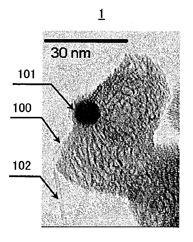
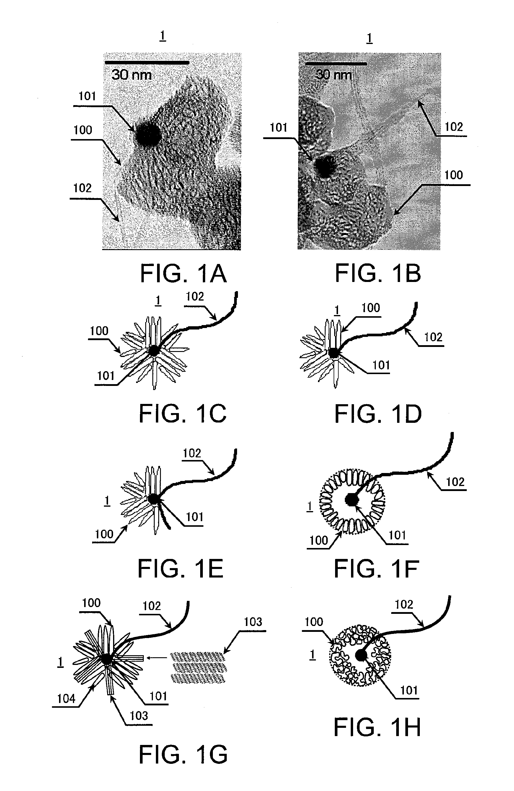
[0068]A carbon target containing a catalyst was evaporated under a constant gas pressure by a laser ablation method while a laser output was varied. Thus, nanotube-nanohorn complexes 1 were produced by way of trial. The following specific steps were performed.

[0069]First, a carbon target containing a catalyst having a diameter of 2.5 cm and a length of 10 cm was placed in a chamber. An inert gas of Ar was supplied so that a gas pressure was 150 Torr (200×102 Pa). The interior of the chamber was held at a room temperature. A flow rate of Ar was set to be 10 L / min. The target containing a catalyst included Co at 0.6 atomic % and Ni at 0.6 atomic %. A target rotation mechanism was provided within the chamber so that a laser beam could continuously be emitted, and was adjusted so that a uniform target surface was produced at the time of continuous emission.

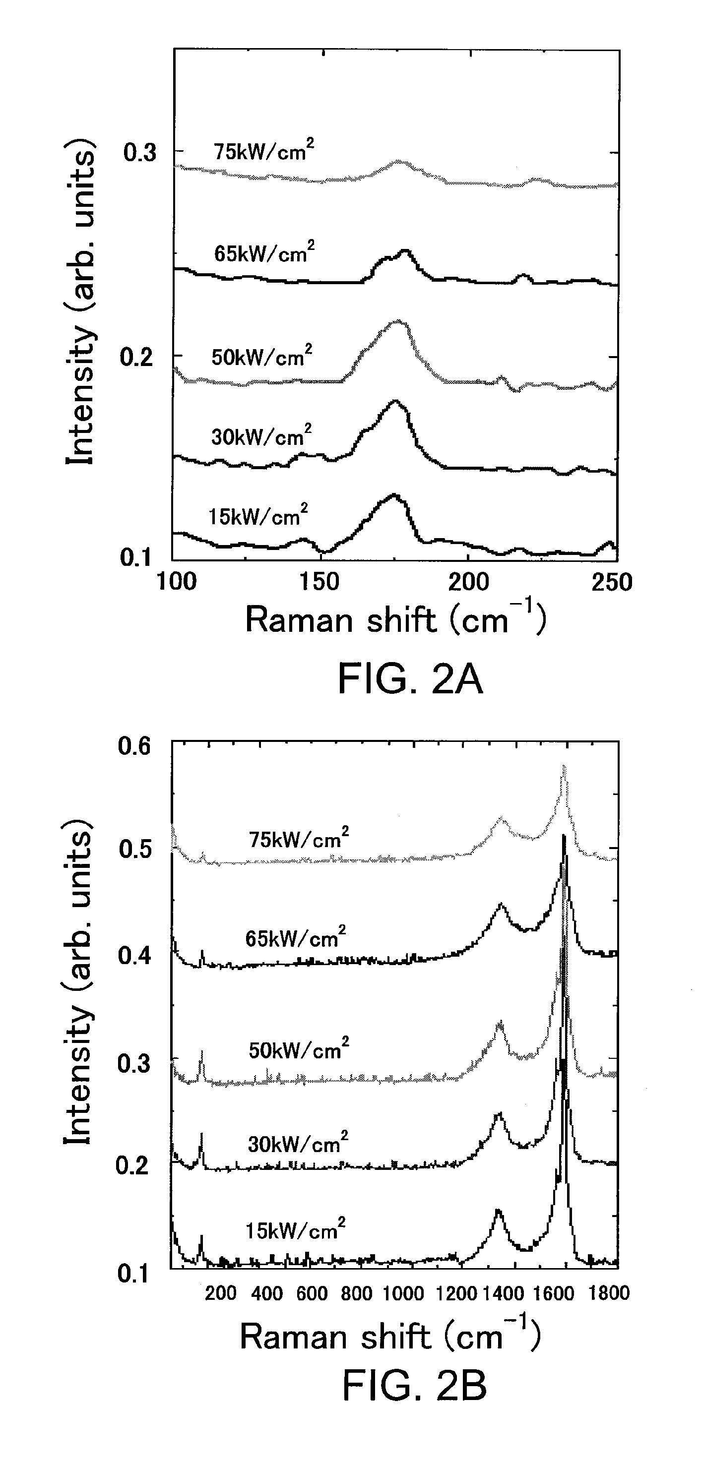
[0070]Then the target containing a catalyst was irradiated with a CO2 laser while the output of the CO2 laser was set to be 15 kW / cm...

example 2

[0074]Under the same conditions as in Example 1 except for a constant laser output (50 kW / cm2) and a varying pressure of Ar, nanotube-nanohorn complexes were produced by way of trial. Measurement of the Raman spectrum of the obtained samples and observation of surfaces of the obtained samples were conducted.

[0075]FIGS. 4A and 4B show the results of the Raman spectrum, FIGS. 5A to 6B show the results of the surface observation.

[0076]It can be seen from FIG. 4A that the RBM was reduced as the pressure was increased from 150 Torr (200×102 Pa) to 760 Torr (1013×102 Pa). Therefore, it can be seen that the amount of a single layer carbon nanotube was reduced. Furthermore, a G / D ratio of FIG. 4B was also deteriorated, exhibiting the same tendency as the RBM results.

[0077]FIGS. 5A and 5B are diagrams simulating transmission electron microscope photographs of samples produced under conditions in which an Ar pressure was 500 Torr (667×102 Pa). It can be seen from those figures that most of th...

example 3

[0079]Under the same conditions as in Example 1 except that a catalyst had a different composition with a constant laser output (50 kW / cm2), Ar pressure (150 Torr (200×102 Pa)), and flow rate (10 L / min), nanotube-nanohorn complexes were produced by way of trial. Measurement of the Raman spectrum of the obtained samples was conducted.

[0080]FIGS. 7A and 7B show the results of the Raman spectrum.

[0081]It can be seen from FIGS. 7A and 7B that a large number of SWNTs (Single-Walled Carbon Nanotubes) were synthesized in a case where Co:Ni=1:1. Furthermore, it appears that carbon nanotubes were hardly synthesized with only Ni.


PUM

PropertyMeasurementUnit
diameteraaaaaaaaaa
diameteraaaaaaaaaa
diameteraaaaaaaaaa

Abstract

An object of the present invention is to provide a nanotube-nanohorn complex having a high aspect ratio, also having high dispersibility, having controlled diameter, and having high durability at a low cost. According to the present invention, a carbon target containing a catalyst is evaporated with a laser ablation method to synthesize a structure including both of a carbon nanohorn aggregate and a carbon nanotube.

Description

BACKGROUND OF THE INVENTION[0001]The present invention relates to a nanotube-nanohorn complex and a method of manufacturing the same.[0002]Carbon nanotubes comprise such characteristics that they have a high aspect ratio, are chemically stable, and are mechanically strong. Therefore, carbon nanotubes have greatly been expected as field emission luminous elements as disclosed in Japanese laid-open patent publications Nos. 2001-143645 (Patent Literature 1) and 2000-86219 (Patent Literature 2) and have diligently been studied.[0003]In most cases where carbon nanotubes are used as field emission elements as disclosed in Japanese laid-open patent publications No. 2007-103313 (Patent Literature 3) and 2007-265749 (Patent Literature 4), it has been customary to mix a binder or the like so as to produce paste for application onto an electrode by spraying, screen printing, or the like. However, the dispersibility of carbon nanotubes is so poor that homogeneous paste cannot be obtained. Accor...

Claims


Application Information

Patent Timeline
Patent Type & Authority Applications(United States)
IPC IPC(8): D01F9/12C23C14/34B82Y30/00B82Y40/00
CPCB82Y30/00Y10T428/2918C01B31/0206H01J1/304H01J9/025H01J2201/30453H01J2201/30469C01B31/0226C01B31/0233C01B31/0293C01B2202/02C01B2202/04C01B2202/36B01J21/18B01J23/28B01J23/30B01J23/40B01J23/70B01J23/74B01J35/0013B82Y40/00C01B32/15C01B32/16C01B32/162C01B32/18C01B2202/06
Inventor YUGE, RYOTAYUDASAKA, MASAKO
Owner NEC CORP
Why Eureka
Try Eureka