Eureka AIR delivers breakthrough ideas for toughest innovation challenges, trusted by R&D personnel around the world.

Method for producing magnetic recording medium and magnetic recording replaying device

Active Publication Date: 2012-08-16
SHOWA DENKO KK
View PDF3 Cites 10 Cited by
  • Summary
  • Abstract
  • Description
  • Claims
  • Application Information

AI Technical Summary

Benefits of technology

[0042]According to the present invention, it is possible to surely remove the mask layer provided on the magnetic layer at high speed, and therefore, it is possible to produce the magnetic recording layer with high flatness in high productivity. Also, in the magnetic recording / reproducing apparatus obtained by using this magnetic recording medium, the further improvement in electromagnetic conversion characteristics can be achieved by taking advantage of high flatness thereof.

Problems solved by technology

As the track density increases, however, magnetic recording information between adjacent tracks begins interfering with each other, which may easily cause a problem that a magnetizing transition area of a border area becomes a noise source that decreases the SNR.
The decrease in the SNR causes a decrease in a bit error rate, which is an obstacle to an improvement in recording density.
There is a problem, however, that the reduced-sized recording bit has a small magnetizing minimum volume per 1 bit and recorded data may disappear due to magnetization reversal caused by heat fluctuation.
In this manner, however, although influence between the tracks can be controlled to the minimum, it is difficult to obtain a sufficient reproduction output and thus to provide a sufficient SNR.
Therefore, there are problems in that a medium is likely to be contaminated during a production step and a production method becomes very complicated.
Therefore, there are problems in that the float attitude and float height of a recording / reproducing head, which performs recording / reproducing while floating on a medium, become unstable.

Method used


Image

  • Method for producing magnetic recording medium and magnetic recording replaying device
  • Method for producing magnetic recording medium and magnetic recording replaying device
  • Method for producing magnetic recording medium and magnetic recording replaying device

Examples


example 1

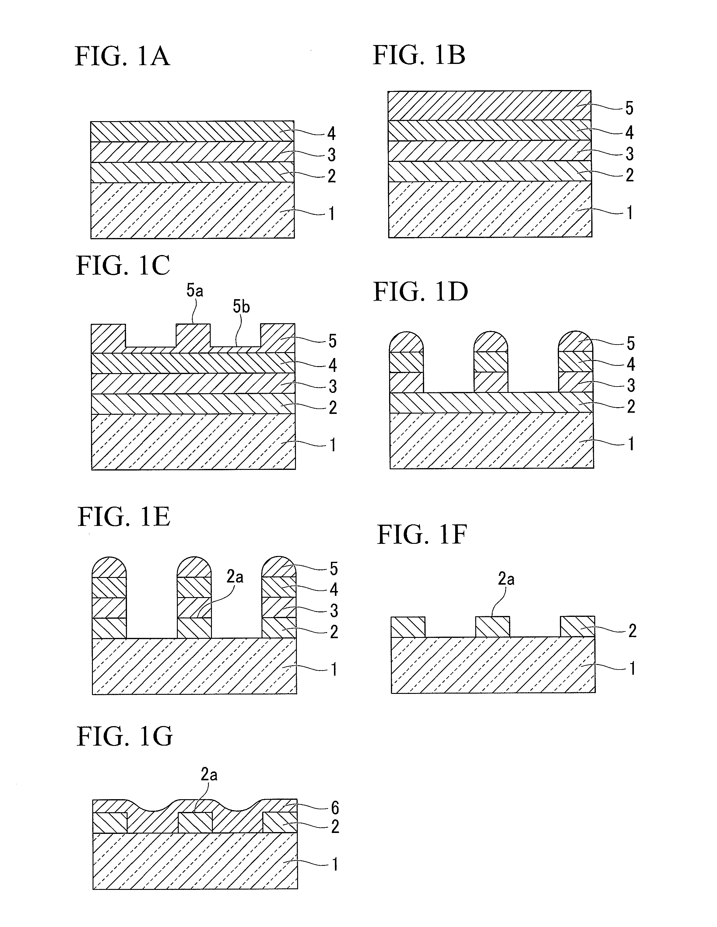
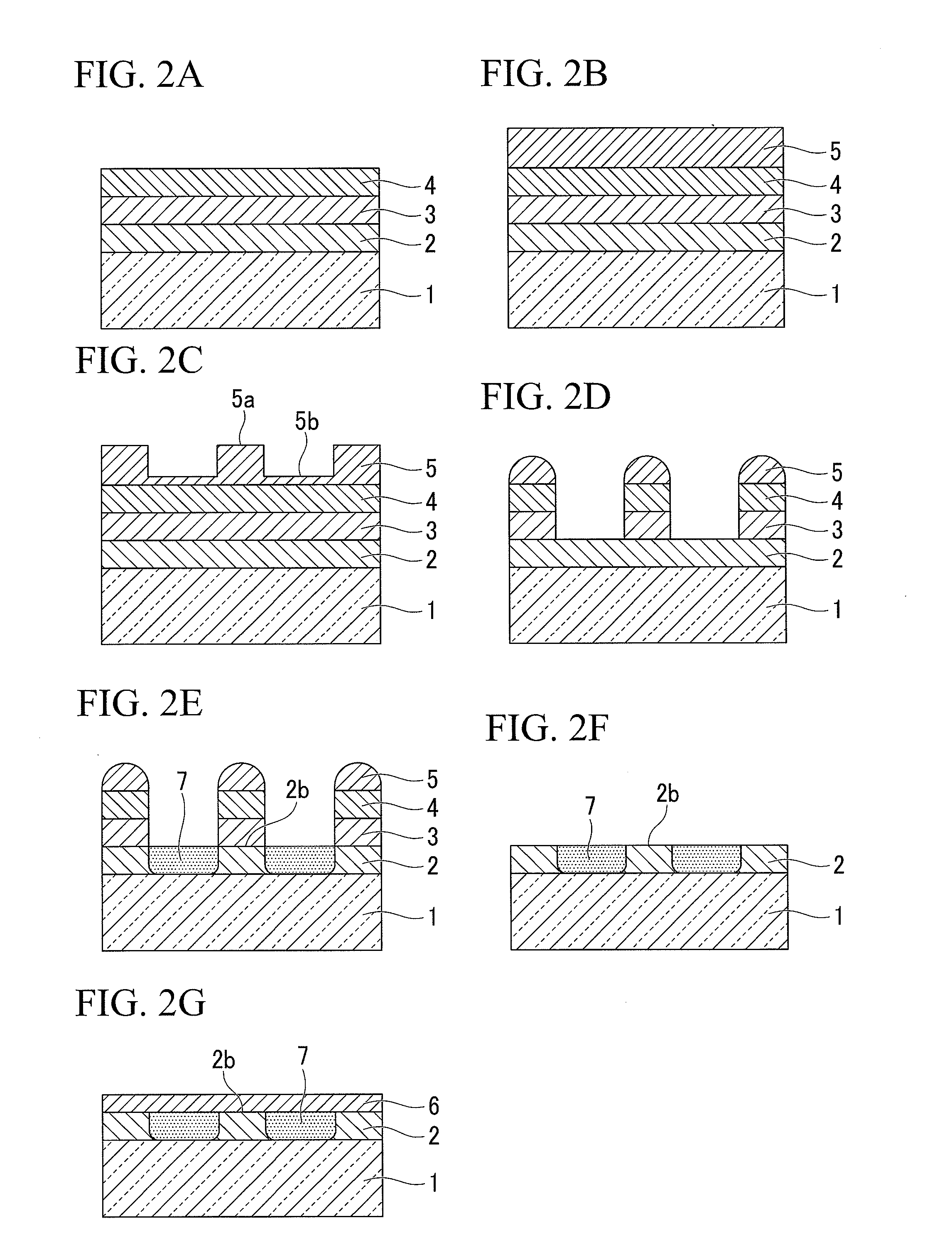
[0143]In Example 1, firstly, a vacuum chamber with a HD glass substrate disposed therein was evacuated to 1.0×10⁻⁵ Pa or less in advance. The glass substrate used herein was formed of a crystallized glass containing Li2Si2O5, Al2O3—K2O, Al2O3—K2O, MgO—P2O5 and Sb2O3—ZnO as constituent components, and had an outer diameter of 65 mm, an inner diameter of 20 mm and an average surface roughness (Ra) of 2 angstroms (=0.2 nm).

[0144]Next, on the glass substrate, the following films were laminated in this order using a DC sputtering method: the FeCoB film with a thickness of 60 nm as the soft magnetic layer, the Ru film with a thickness of 10 nm as the intermediate layer, the 70Co-5Cr-15Pt-10SiO2 alloy film with a thickness of 15 nm and the 70Co-5Cr-15Pt alloy film with a thickness of 14 nm as the recording magnetic layer, the CrTi film with a thickness of 2 nm and the Mo film with a thickness of 5 nm as the dissoluble layer, and the carbon film with a thickness of 30 nm as the mask layer.

[...


PUM


Abstract

A production method of a magnetic recording medium of the present invention includes: a step of forming a magnetic layer (2) on a non-magnetic substrate (1); a step of forming a dissoluble layer (3) on the magnetic layer (2); a step of forming a mask layer (4) on the dissoluble layer (3); a step of patterning the dissoluble layer (3) and the mask layer (4) to a shape corresponding to a magnetic recording pattern (2a); a step of performing a partial modification or removal of the magnetic layer (2) by use of the patterned mask layer (4); and a step of dissolving the dissoluble layer (3) with a chemical agent so as to remove the dissoluble layer (3) together with the mask layer (4) formed thereon from the top of the magnetic layer (2), wherein the magnetic recording medium has the magnetically-separated magnetic recording pattern (2a).

Description

TECHNICAL FIELD[0001]The present invention relates to a method for producing a magnetic recording medium for use in a hard disk drive (HDD) or the like, and a magnetic recording and reproducing apparatus.[0002]This application claims priority on Japanese Patent Application No. 2009-241491, filed Oct. 20, 2009, the content of which is incorporated by reference herein.BACKGROUND ART[0003]Recently, the applicability of magnetic recording apparatuses such as magnetic disk devices, flexible disk devices and magnetic tape devices has increased significantly, and the importance thereof has also increased. Also, the recording density of magnetic recording media used for these devices has been increased significantly. With the introduction of an MR head and a PRML technology, surface recording density has improved still more significantly. In recent years, GMR heads and TMR heads have also been introduced, which further increase the surface recording density by about 1.5 times per year.[0004...

Claims


Application Information

Patent Timeline
IPC IPC(8): G11B5/52G11B5/842
CPCB05D1/32G11B5/855
Inventor UEDA, MANABUMURAKAMI, YUJISAKAWAKI, AKIRAWANG, ZHIPENG
Owner SHOWA DENKO KK
Why Eureka
Eureka Blog
Learn More