P2p-engine

a technology of p2p engine and overlay configuration, applied in the field of p2p engine, can solve problems such as poor overlay configuration, and achieve the effect of enhancing the overall system performan

Active Publication Date: 2012-08-16
PEERIALISM
View PDF25 Cites 22 Cited by
  • Summary
  • Abstract
  • Description
  • Claims
  • Application Information

AI Technical Summary

Benefits of technology

[0006]An object of the present, invention is to connect peers in an overlay network in an efficient manner such that overall system performance is enhanced.
[0008]To this end, a P2P overlay network, which comprises a streaming source and a plurality of peers arranged in distribution layers, is arranged such that the total number of distribution layers of the overlay network is reduced. First, the upload capacity of each individual peer is determined and a maximum number of overlay peers to which said each individual peer can upload is calculated. Then, the peers are arranged in hierarchical order in relation to the streaming source on the basis of the maximum number of peers to which each individual peer can upload data. A higher number results in the individual peer being arranged in a distribution layer closer to the streaming source while a lower number results in the individual peer being arranged in a distribution layer further from the streaming source. Thus, the total number of distribution layers of the overlay network is reduced.
[0010]Since all peers are sorted based on the maximum number of other peers to which they can upload data given a certain upload capacity, known as the “seat count”, the problem of having large-capacity peers located in a distribution layer far from the streaming server ears be eliminated. After having sorted all overlay peers, the peers with high seat count are seated in the first distribution layer, and the process continues until all peers have been placed in the required distribution layer. This not only facilitates good upload bandwidth utilization, but also results in an overlay that has a reduced number of distribution layers. Hence, the average number of hops from the streaming server to the peers is reduced, which directly translates info smaller playback delays. This is highly advantageous in a P2P network.
[0011]In an embodiment of the present invention, the number of peers placed in a distribution layer being closest to the streaming source is selected to be as low as possible while still being able to provide a total streaming bandwidth satisfying a predetermined bandwidth threshold value. In other words, large-capacity peers are typically placed in the first distribution layer, i.e. the layer being closest to the streaming server, and the number of peers in the first distribution layer is held at a minimum while providing sufficient bandwidth for the rest of the network. Given a minimum threshold requirement which the first distribution layer must be capable of providing with respect to bandwidth, the number of peers in the first layer is selected such that this requirement is met. For instance, if the minimum bandwidth requirement of the first distribution layer is set to 512 kbps and each peer to be placed in the first layer is capable of uploading 256 kbps, then two peers should be placed in the first distribution layer such that predetermined bandwidth criteria can be met. Thus, minimizing the number of peers placed in the first distribution layer advantageously prevents sub-optimizations with respect to provided bandwidth capacity for the rest of the network; the number of peers placed in the first distribution layer is selected such that sufficient bandwidth is provided to the remaining peers in the P2P network, while the bandwidth capacity of the first layer is not oversized.
[0013]In yet a further embodiment of the present invention, peers which previously have been reported to fail other downloading peers will be penalized, i.e. moved down in the hierarchy, and thus placed in a distribution layer further away from the streaming source, potentially even further away than what is justified by the determined number of other overlay peers to which the penalized peer uploads data. This is advantageous in order to maintain system robustness.

Problems solved by technology

From a bandwidth perspective, this is not a good overlay configuration.

Method used


Image

  • P2p-engine
  • P2p-engine
  • P2p-engine

Examples


Embodiment Construction

High-Level Architecture

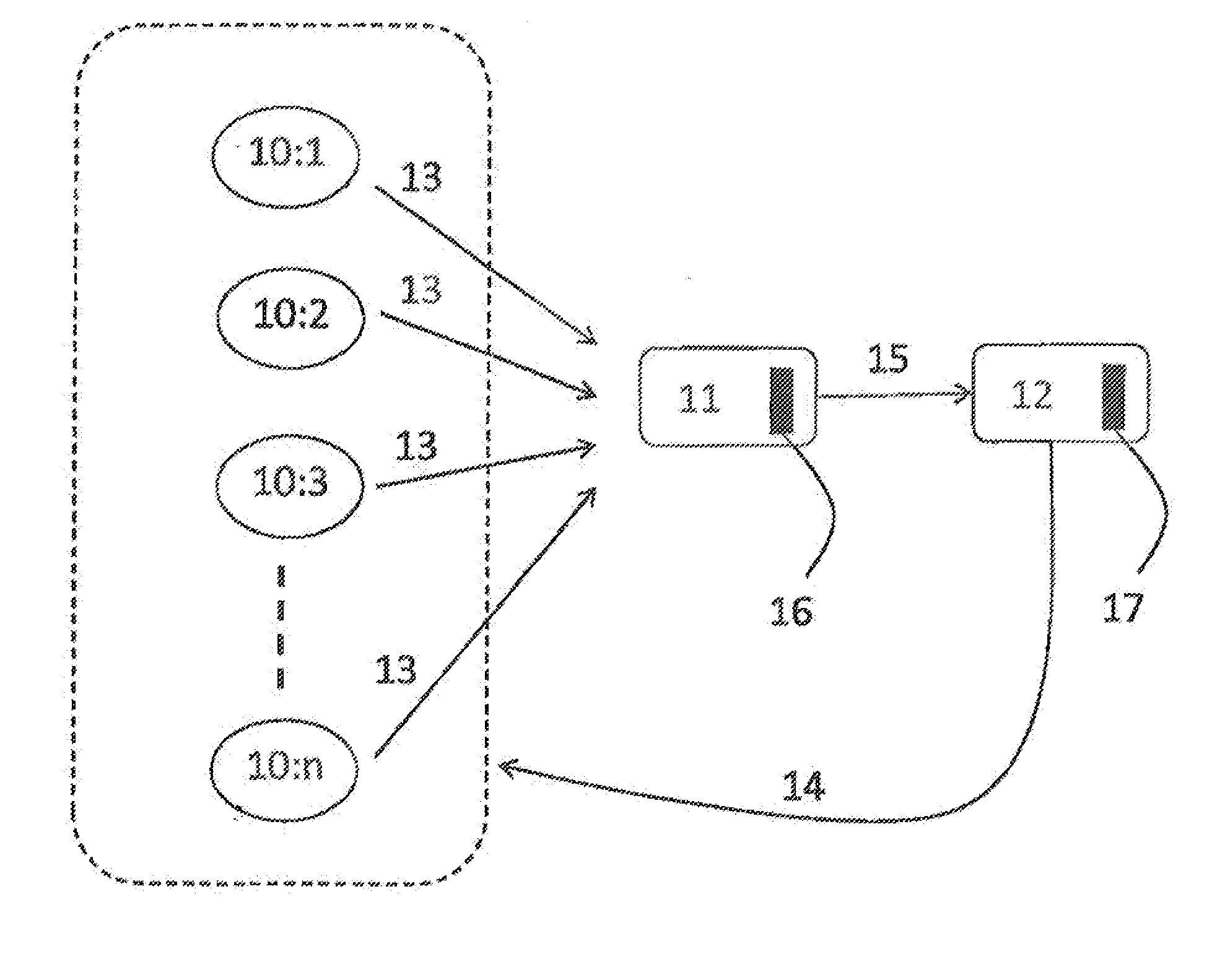
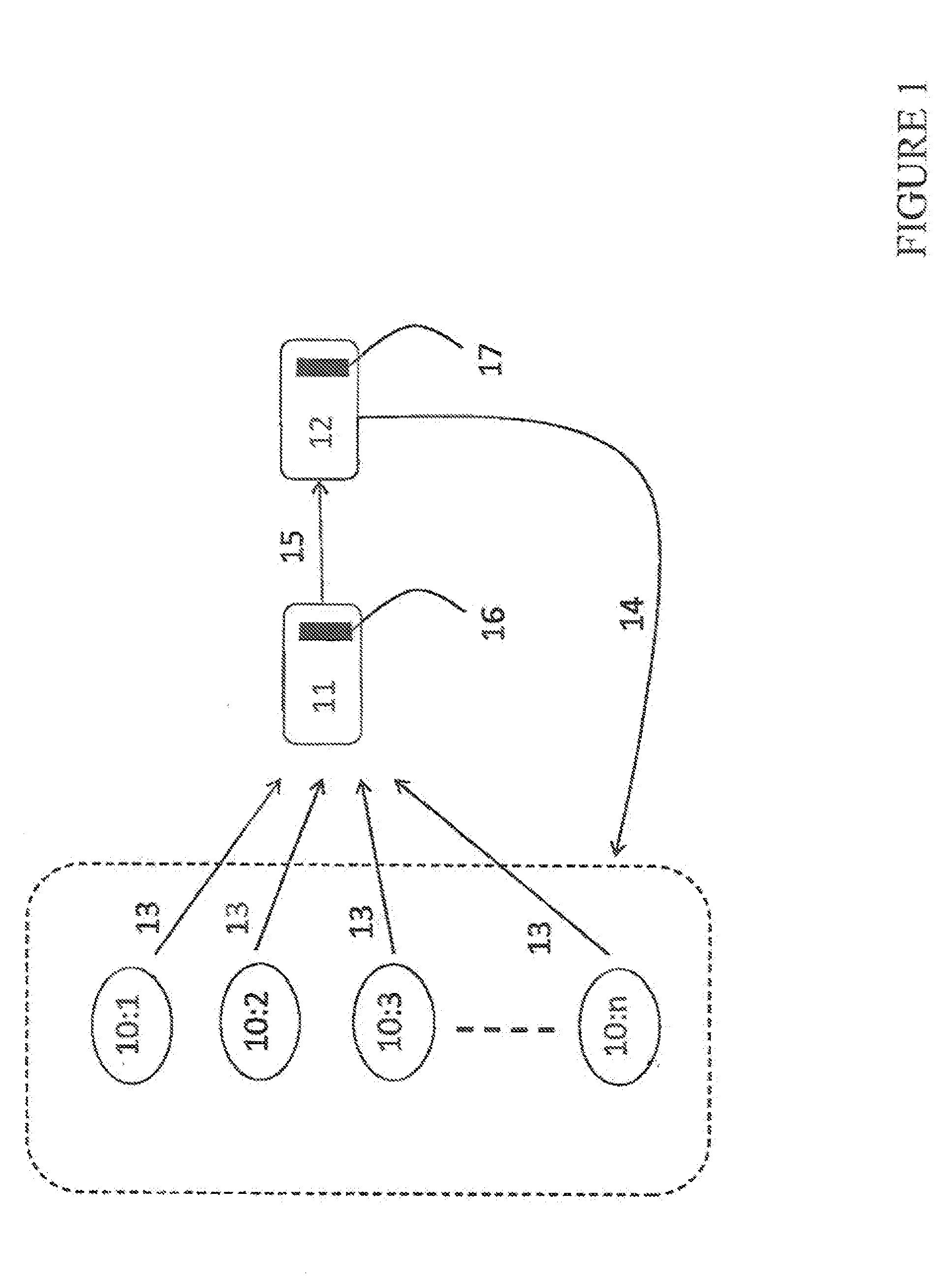
[0023]FIG. 1 shows a prior art P2P system in the form of a plurality of peers 10:1, 10:2, 10:3, . . . , 10:n and a so called tracker 11 with which the peers communicate. Further, FIG. 1 shows a connectivity engine 12 in accordance with the present invention, which is connected to the tracker and the peers. FIG. 1 is by means of illustration only: the engine could functionally be part of the tracker and from hardware point of view be located in the same functional block. Both the tracker and the engine are typically devices with computing facilities embodied in the form of processors 16, 17, Thus, the tracker and the engine are typically implemented as computers executing appropriate software stored in associated memory for procuring required functionality. However, other suitable devices with computing capabilities could be used, e.g. an application specific integrated circuit (ASIC), a field programmable gate array (FPGA), a complex programmable logic device ...


PUM


Abstract

A peer-to-peer (P2P) overlay network, which comprises a streaming source and a plurality of peers arranged in distribution layers, is arranged such that the total number of distribution layers of the overlay network is reduced. First, the upload capacity of each individual peer is determined and a maximum number of overlay peers to which said each individual peer can upload is calculated. Then, the peers are arranged in hierarchical order in relation to the streaming source on the basis of the maximum number of peers to which each individual peer can upload data. A higher number results in the individual peer being arranged in a distribution layer closer to the streaming source while a lower number results in the individual peer being arranged in a distribution layer further from the streaming source. Thus, the total number of distribution layers of the overlay network is reduced.

Description

BACKGROUND ART[0001]The use of the Internet's infrastructure for video streaming has proliferated over the last few years as broadband internet access is becoming widely available. Many commercial deployments have relied on hardware based IP multicast routers that are placed strategically within networks maintained by Internet Service Providers (ISPs) to stream video traffic. However, such hardware based approaches are quite expensive to setup and difficult to extend beyond the bounds of a single ISP.[0002]To circumvent the problem of having to deploy and setup expensive multicast routers, an alternative approach is to strategically place high availability servers close to target customers and have them download from those servers. Such an approach also suffers from the expenses of buying the necessary bandwidth from Content Delivery Networks (CDNs). Such bandwidth may often not quite match the customers' demands, resulting in either over or under investment.[0003]In order to attain...

Claims


Application Information

Patent Timeline
Patent Type & Authority Applications(United States)
IPC IPC(8): G06F15/16
CPCH04L67/1044H04L67/1089
Inventor EL-BELTAGY, MOHAMMED
Owner PEERIALISM
Why Eureka
Try Eureka