Vertical turning-milling complex machining center

Active Publication Date: 2012-08-23
KEDE NUMERICAL CONTROL CO LTD
View PDF8 Cites 45 Cited by
  • Summary
  • Abstract
  • Description
  • Claims
  • Application Information

AI Technical Summary

Benefits of technology

[0040]In the present invention, the uniaxial rotating table is disposed between two ball screws, an ideal but virtual gravity center is formed when the rotating table is no-load, while an effect that is completely identical to the passage of an actual drive force through a gravity center could be generated, which perfectly inhibits the vibration and bending generated as being driven by the X axis, no change of the gravity center occurs even if the uniaxial rotating table moves at high speed in the X-axis direction, so as that stable driving is implemented. Moreover, the equipment in the present invention may also adopt three line rails, namely, besides the line rails installed at the both sides of the uniaxial rotating table, a line rail is further installed at the center of the bottom portion of the uniaxial rotating table to play the role of supporting, in this way, deformation could be minimized even if the rotating table is under load;
[0041]The tool holder in the present invention, which is directly driven by the torque motor, is connected to the tool clamping mechanism of the machine tool via the tool handle, and is power inputted by the butt joint of the self-sealing type electrical interface installed on the tool holder with the electrical interface assortedly installed on the tool clamping mechanism of the machine tool so as to be directly driven by the torque motor to machine a workpiece, that is to say, when power is switched on, the motor installed inside the inner cavity of the tool holder drives the core shaft of the tool to rotate directly, and the tapered holes at the front end of the core shaft for connecting with the tool as well as the locking nuts can clamp a variety of required tools conveniently.
[0042]Therefore, the equipment has extra milling and drilling ability and can carry out axial or radial machining so as to meet the machining d

Problems solved by technology

Therefore, a workpiece needs to be positioned, clamped and set with respect to cutters repeatedly among a plurality of machine tools during actual machining, which would cause time waste and reduce production efficiency, and plenty of unnecessary errors are generated midway due to the continuous replacement and adjustment of cutters.
While functions that a lot of traditional machine tools fail to achieve have been achieved by applying these mechanical transmission technologies to key parts of a machine tool, such as a C-axis rotating machine tool work table and a B-axis pendulum machine tool milling head and the like, these technologies functioning simply by mechanical transmission could not keep pace with the development of modern international machine tool manufacturing industry in the aspects of speed, precision and service life.
In addition, a majority of the complex multi-axis machine tools at home and abroad adopt a single driving center driving, i.e. one ball screw, for driving key functional parts, such as a uniaxial rotating work table, but in this kind of structure, a driving force cannot act upon the gravity center of a moving member accurately during the machining course.
Therefore, there is a tendency to generate a twisting motion under high cutting speed, especially under large feeding speed and high rotating speed of a rotating table.
This unavoidable twisting motion and the effect of inertia generated by the moving member is to lead to the vibration of the machine tool, which causes machine tool mem

Method used


Image

  • Vertical turning-milling complex machining center
  • Vertical turning-milling complex machining center
  • Vertical turning-milling complex machining center

Examples


embodiment 1

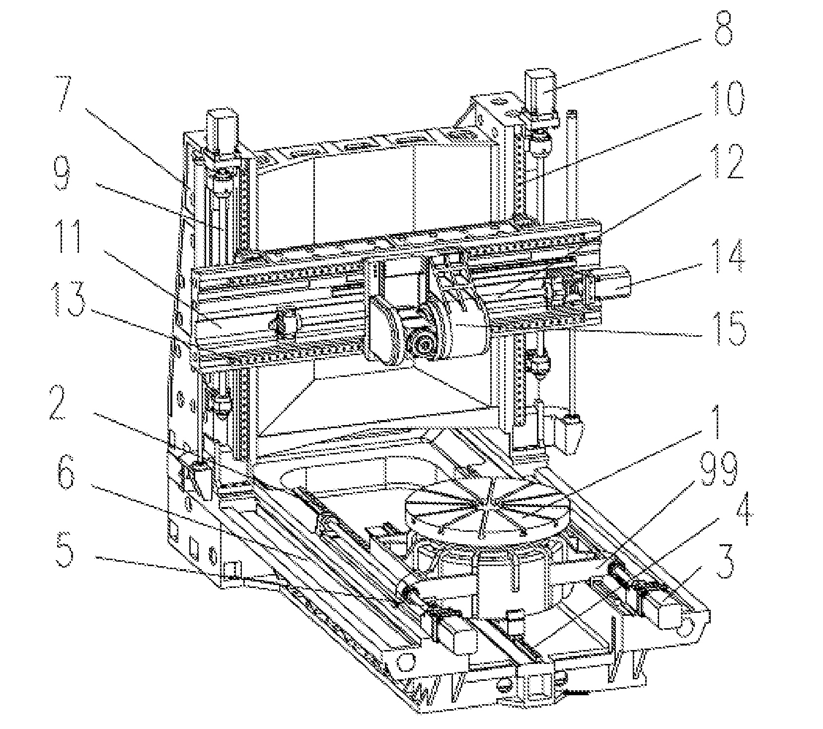
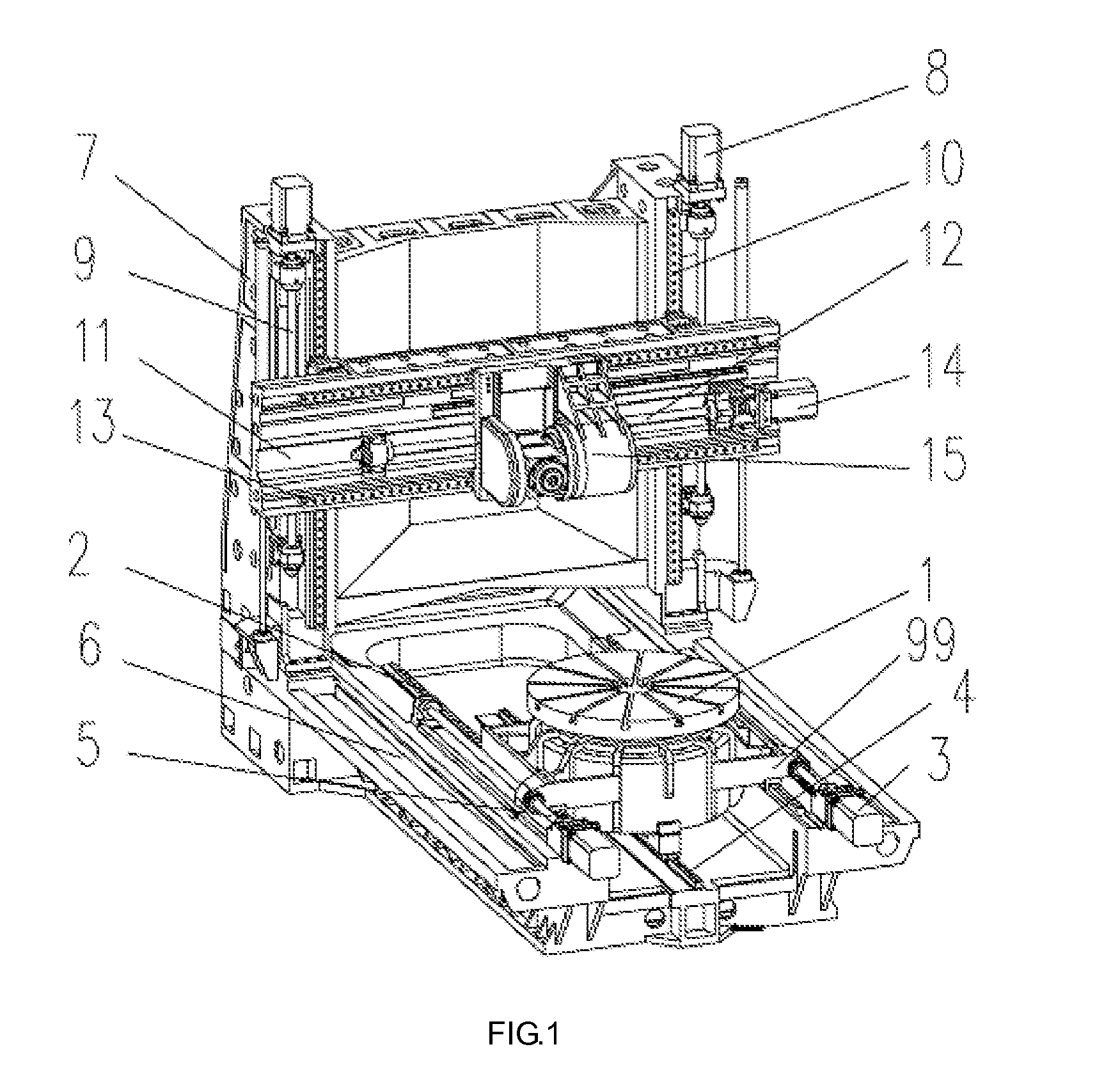
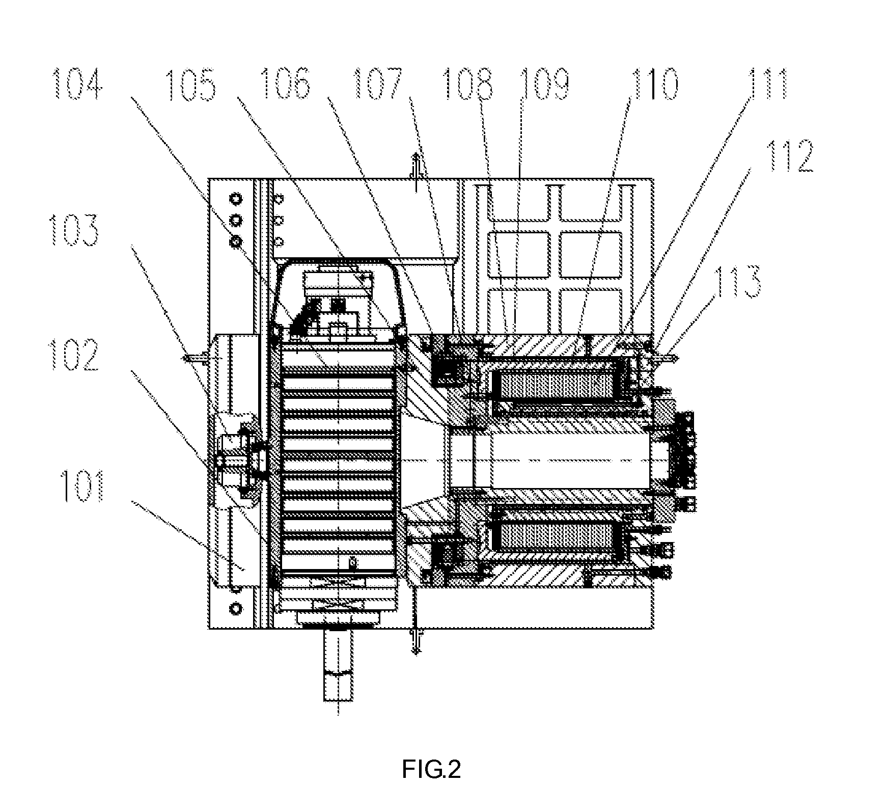
[0070]A vertical turning and milling complex machining center, as shown in FIG. 1, comprises: a bed body 6 which is horizontally disposed, two stand columns 7 fixed at left and right sides at one end of the bed body respectively and vertical to the bed body; two X-axis side portion supporting line rails 2 and two X-axis guide screws 5 respectively disposed at left and right sides of the bed body 6 corresponding to the two stand columns; a uniaxial rotating table 1 is located on the two X-axis side portion supporting line rails 2, and a transverse saddle of the uniaxial rotating table 1 fitly connects with the two X-axis guide screws 5 in a manner of reciprocating movement along the X axis; X-axis drive motors 3 are respectively disposed at the end portions of the X-axis guide screws; the uniaxial rotating table 1 is driven directly by a first external rotor torque motor 204 at the lower portion thereof;

[0071]First Z-axis side portion supporting line rails 10 and first Z-axis guide s...

embodiment 2

[0078]On the basis of the Embodiment 1, the vertical turning and milling complex machining center, as shown in FIG. 7 and FIG. 8, further includes a vertical tool post component 17;

[0079]The vertical tool post component 17 includes an elongated vertical tool post 171, a tool post base 172, and a second Z-axis supporting line rail 176 and a second Z-axis guide screw pair disposed at both sides of opposite surfaces between the vertical tool post and the tool post base, wherein the second Z-axis guide screw 1751 is connected with a second Z-axis drive motor 173 via a shaft coupling 174;

[0080]The 172, as shown in FIG. 10, is fixed at a single pendulum milling head 15 side of the transverse sliding table 16 and reciprocates along with the transverse sliding table 16 in the Y-axis direction;

[0081]The vertical tool post 171, as shown in FIG. 11, is supported by the second Z-axis supporting line rail 176 and reciprocates in the Z-axis direction under the driving of the second Z-axis guide s...


PUM

PropertyMeasurementUnit
Gravityaaaaaaaaaa
Stiffnessaaaaaaaaaa
Stabilityaaaaaaaaaa

Abstract

A vertical turning-milling complex machining center comprises a horizontally-arranged bed body (6) and a vertically-arranged column (7). The bed body (6) is provided with an X-axis lateral supporting linear track (2) and an X-axis guide screw (5). The bed body (6) is also provided with a uniaxial rotating table (1) which can reciprocate and is driven directly by a first external rotor torque motor. The column (7) is vertically provided with a Z-axis lateral supporting linear track (10), a Z-axis guide screw (9) and a crossbeam (11) that reciprocates up and down. The crossbeam (11) is provided with a transverse Y-axis linear track (13), a Y-axis guide screw (12) and a single-pendulum milling head seat frame that can reciprocate along the Y-axis guide screw (12). The single-pendulum milling head is driven directly by a second external rotor torque motor. The vertical turning-milling complex machining center uses direct-drive technology applied to a B-axis and a C-axis, the motor torque is greatly increased and functional parts can stably operate, therefore the integral rigidity and stability of the machining center are improved.

Description

TECHNICAL FIELD[0001]The present invention relates to machine tools, more particularly to a vertical turning and milling complex machining tool.BACKGROUND[0002]With the fast development of automobile, national defense, aviation, aerospace and other industries as well as the application of new materials like aluminum alloy, there are increasingly high requirements on combined machine tools. As taking typical parts in aviation industry, such as a turbine case and a fan case, for example, turning, milling, radial drilling and boring and other machining operations are required simultaneously in the process for such parts, and high precision is needed. Therefore, a workpiece needs to be positioned, clamped and set with respect to cutters repeatedly among a plurality of machine tools during actual machining, which would cause time waste and reduce production efficiency, and plenty of unnecessary errors are generated midway due to the continuous replacement and adjustment of cutters. The p...

Claims


Application Information

Patent Timeline
IPC IPC(8): B23P23/02
CPCB23P23/02Y10T409/309296B23Q1/4819B23Q1/4842B23Q5/40B23Q1/012B23Q5/10B23C1/12B23B3/22B23C9/005B23B11/00Y10T409/307672Y10T29/5114Y10T409/308288Y10T409/305656Y10T82/2511Y10T29/5109Y10T409/305768Y10T409/307728Y10T409/30448B23Q1/4804
Inventor YU, DEHAICAI, CHUNGANGREN, ZHIHUIZHANG, WENFENGCHEN, HUZHENG, JUNMINGUO, QIANGZOU, TAOLI, JINGMINGQU, PENGLIN, YANG
Owner KEDE NUMERICAL CONTROL CO LTD
Why Eureka
Try Eureka