Gas sensor element and gas sensor

a technology of gas sensor and element, applied in the direction of instruments, material electrochemical variables, measurement devices, etc., can solve the problem that the adhesion strength between the inner and outer layers of the above-disclosed porous protection layer is not sufficient, and achieves the effect of sufficient adhesion strength

Active Publication Date: 2012-08-23
NGK SPARK PLUG CO LTD
View PDF2 Cites 48 Cited by
  • Summary
  • Abstract
  • Description
  • Claims
  • Application Information

AI Technical Summary

Benefits of technology

[0005]It is therefore an object of the present invention to provide a gas sensor element having a multilayer porous protection layer capable of enhancing an interlaminar adhesion strength while maintaining thermal insulation effect. It is also an object of the present invention to provide a gas sensor using the gas sensor element.

Problems solved by technology

However, the above-disclosed porous protection layer does not attain a sufficient strength of adhesion between the inner and outer layers just by setting the porosity of the inner layer higher than that of the outer layer.
Further, the above-disclosed porous protection layer does not exert sufficient thermal insulation effect so that heat may be taken away from the gas sensing portion when the gas sensor element gets wet with water.

Method used


Image

  • Gas sensor element and gas sensor
  • Gas sensor element and gas sensor
  • Gas sensor element and gas sensor

Examples


example

[0064](Sample Production)

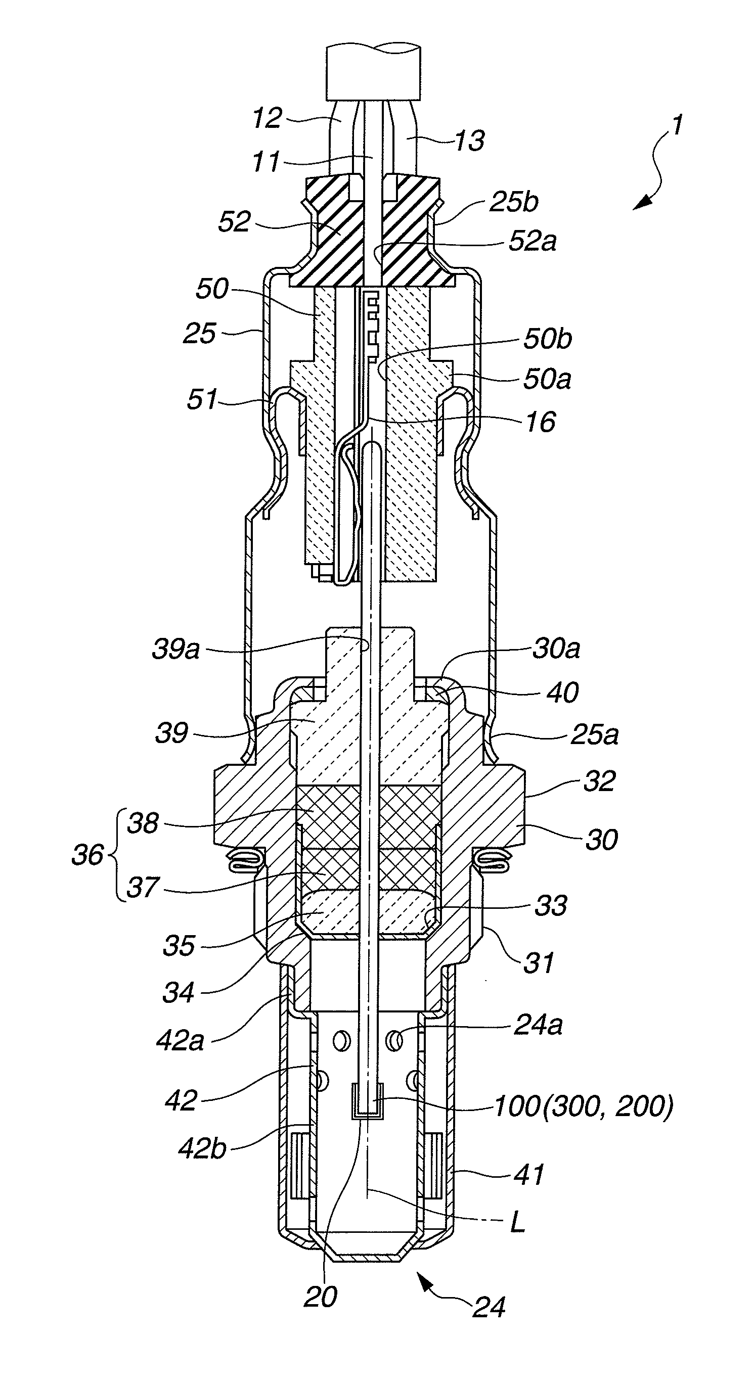
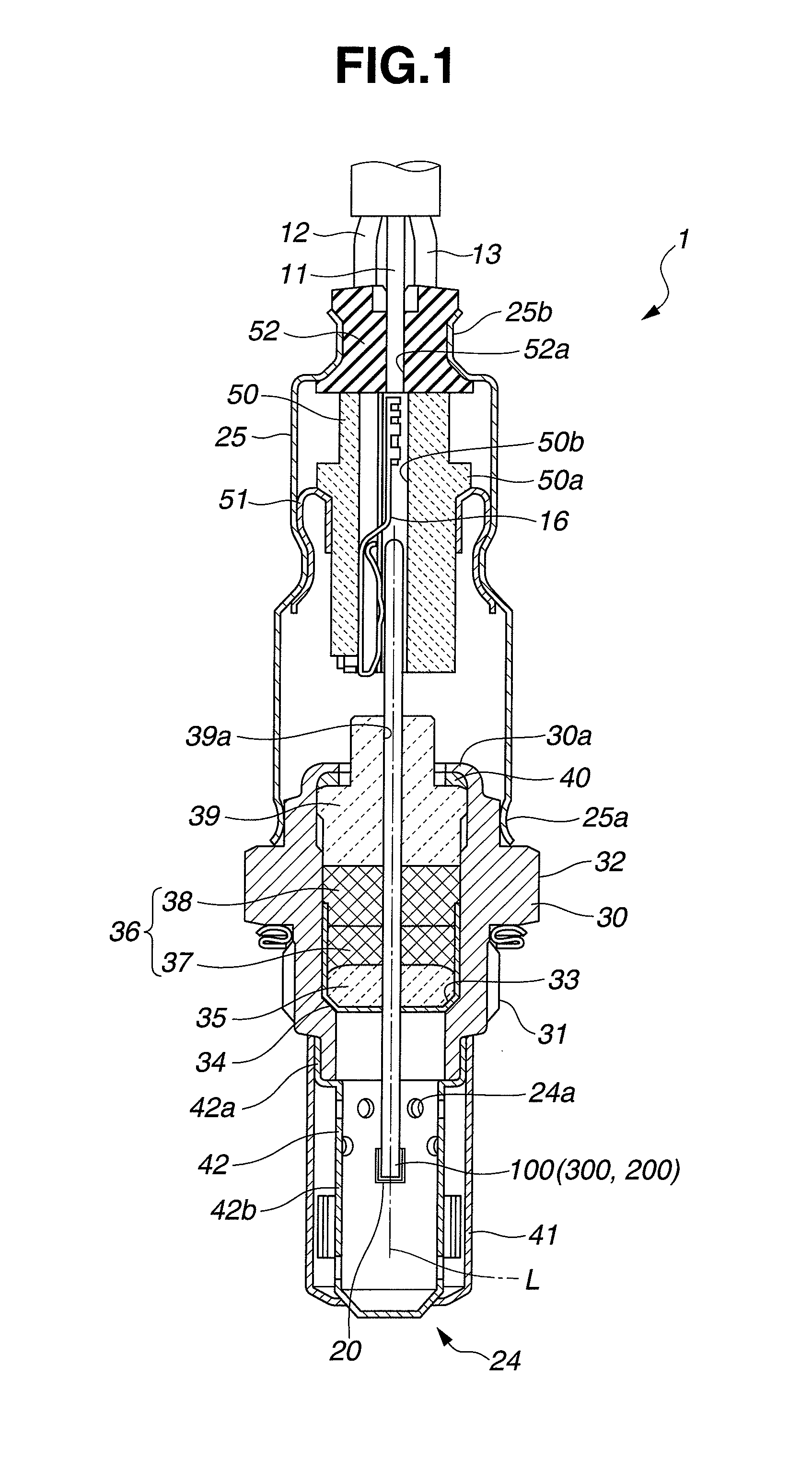
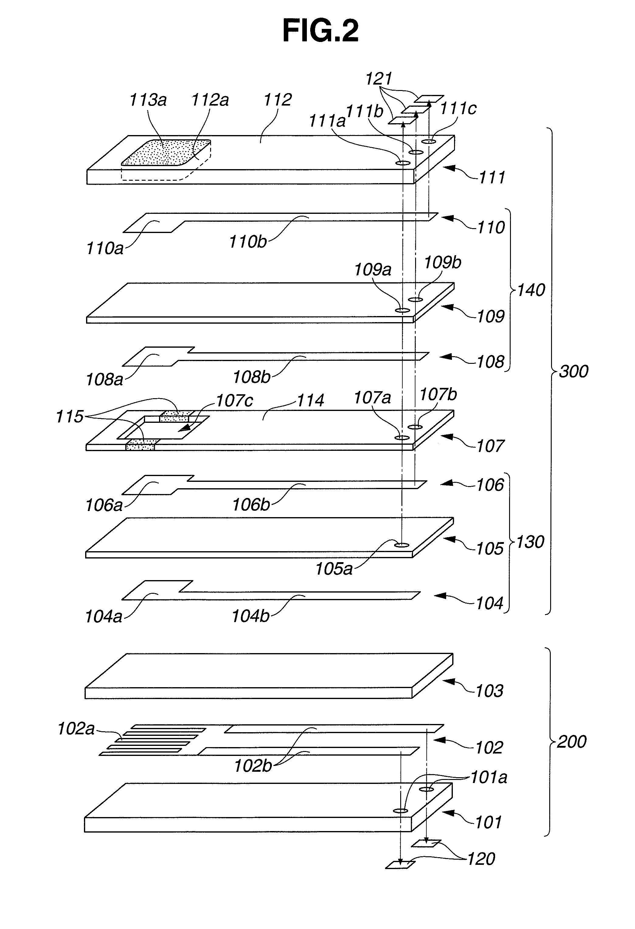
[0065]Samples of the plate-shaped gas sensor element 100 shown in FIGS. 1 and 2 were each produced by forming the porous protection layer 20 as follows.

[0066]A slurry A was prepared as an inner-region slurry by mixing 40 vol % of alumina powder (particle size distribution: D10=0.24 μm, D50=0.40 μm, D90=0.60 μm), 60 vol % of carbon powder (particle size distribution: D10=10.5 μm, D50=20.6 μm, D90=42.2 μm) and 10 vol % of separately prepared alumina sol with ethanol. The prepared slurry A was adjusted to an appropriate viscosity and applied by dipping (immersion) process to the entire circumference (four sides) of the front end portion of the sensor element body (sensing unit 300 and heating unit 200) in such a manner that the coating of the slurry A was 300 μm in thickness. The applied slurry coating was dried in a dryer at 200° C. for several hours, thereby removing excessive organic solvent from the slurry coating. The dried slurry coating was then sintered...


PUM

PropertyMeasurementUnit
porosityaaaaaaaaaa
porosityaaaaaaaaaa
porosityaaaaaaaaaa

Abstract

There is provided a gas sensor element for detecting the concentration of a specific gas component in gas under measurement, which includes a plate-shaped element body and a porous protection layer. The element body has, at one end portion thereof, a gas sensing portion formed with a solid electrolyte substrate and a pair of electrodes. The porous protection layer has a porous structure formed of ceramic particles and surrounds at least the circumference of the one end portion of the element body. In the present invention, the porous protection layer has an inner region, an intermediate region and an outer region laminated together in order of mention from the element body toward the outside. The intermediate region has a porosity lower than those of the inner and outer regions. There is also provided a gas sensor with such a gas sensor element.

Description

BACKGROUND OF THE INVENTION[0001]The present invention relates to a gas sensor element for detecting the concentration of a specific gas component in gas under measurement such as combustion gas or exhaust gas of an internal combustion engine or a combustor etc. and to a gas sensor using the gas sensor element.[0002]Hereinafter, the terms “front” and “rear” are used with respect to the axial direction of a gas sensor (gas sensor element) for purposes of description. These terms are illustrative and are not intended to limit the scope of the present invention.[0003]There has been used a gas sensor having a gas sensor element for detecting the concentration of a specific gas component such as oxygen in exhaust gas of an internal combustion engine. The gas sensor element includes a plate-shaped element body having, at a front end portion thereof, a gas sensing portion provided with a solid electrolyte substrate and a pair of electrodes. When the front end portion of the gas sensor elem...

Claims


Application Information

Patent Timeline
Patent Type & Authority Applications(United States)
IPC IPC(8): G01N27/26
CPCG01N27/4077
Inventor ONKAWA, MASAKIOTSUKA, SHIGEHIROOYA, SEIJITERAMOTO, SATOSHITANAKA, KUNIHARUMITSUOKA, TAKESHI
Owner NGK SPARK PLUG CO LTD
Why Eureka
Try Eureka