
Dynamic Management of Random Access Memory

a random access memory and dynamic management technology, applied in the field of computer systems, can solve the problems of significant computational resources, high computational performance, and significant increase in the cost of the communication system, and achieve the effects of improving the performance of the computer system, reasonable development period, and limited cos

Inactive Publication Date: 2012-08-23
ST ERICSSON SA
View PDF8 Cites 3 Cited by
  • Summary
  • Abstract
  • Description
  • Claims
  • Application Information

AI Technical Summary

Benefits of technology

[0012]There is therefore a need to improve the performance of computer systems while ensuring a limited cost and a reasonable development period, particularly when adding new functionalities to an existing platform.

Problems solved by technology

In communication systems for example, very high computational performance is expected while maintaining a limited cost and the shortest possible development time for the communication system.
These real-time functionalities require significant computational resources because they involve the processing of a large amount of data within a minimum amount of time.
This solution significantly increases the cost of the communication system, however.
In addition, when it involves incorporating new real-time features into an existing hardware system that has only one processor, this solution is not a real possibility because it involves completely revising the system structure, which has a cost and involves a long development period.
However, this solution involves increasing the size of the components on the silicon of the chip in which the system is implanted.
In addition, there is a limit to how much the size of the L1 cache can be increased, beyond which the gain in computational speed becomes insignificant because the number of instructions for fetching specific data from the L1 cache becomes too high.

Method used


Image

  • Dynamic Management of Random Access Memory
  • Dynamic Management of Random Access Memory
  • Dynamic Management of Random Access Memory

Examples


Embodiment Construction

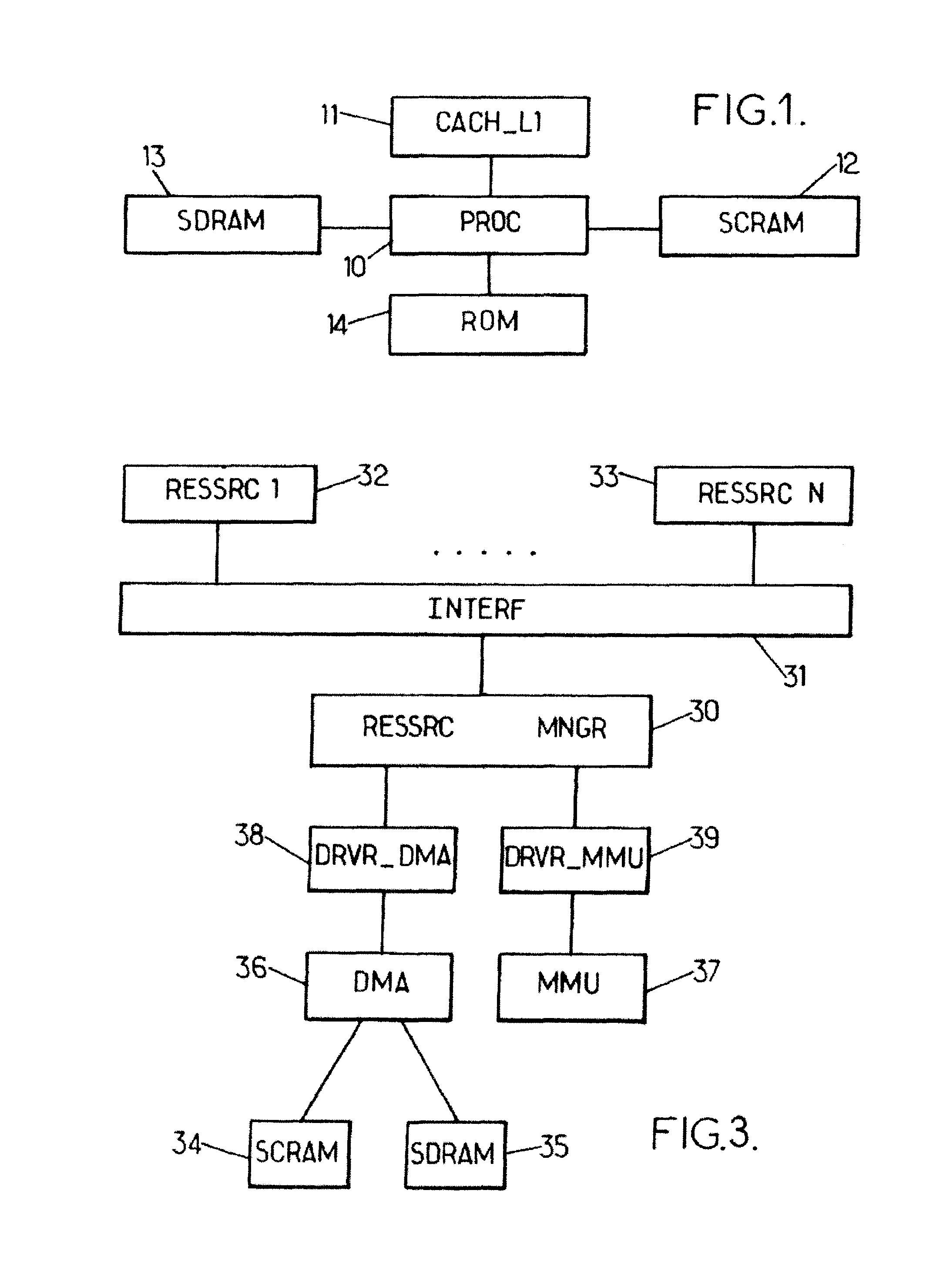
[0065]A processing unit structure of a computer system is described very schematically, with reference to FIG. 1.

[0066]In this structure, there is a processor 10 in charge of executing more or less basic instructions in the context of the more general execution of a computer program.

[0067]The processor 10 has different types of memory available for this purpose.

[0068]It has several cache memories available to it. This type of memory is used to store data temporarily that are useful for the execution of the instructions. This type of memory can store data to be processed such as the operands of operations to be executed by the processor, or the identification of operations to be performed. This memory has very good performance in terms of access time, and is used for copying the data used to bring them close to the processor.

[0069]Among such cache memory is the “L1” cache 11. This is the cache closest to the processor, and is also the highest performance memory in terms of access tim...


PUM


Abstract

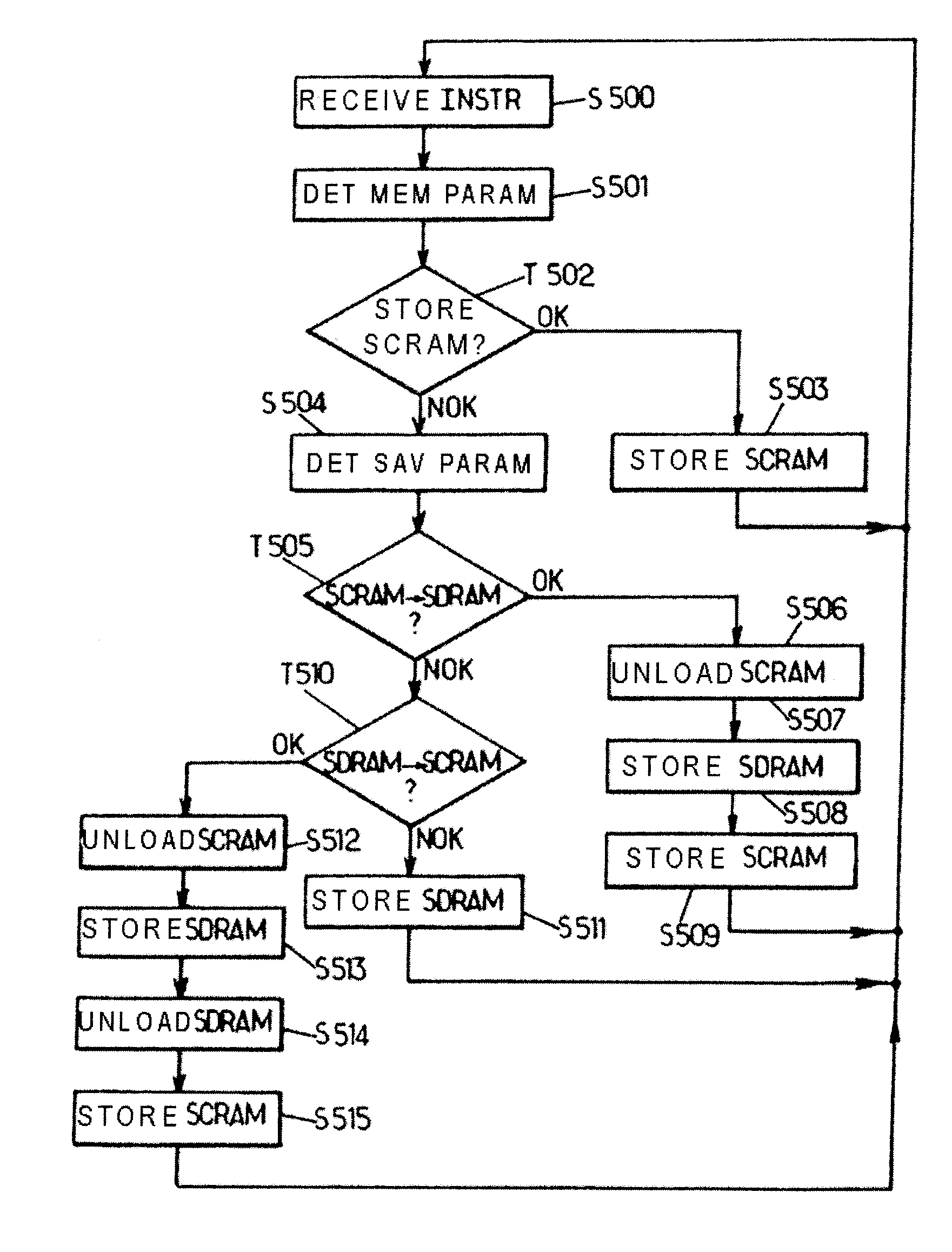
The invention proposes a method for managing random access memory in a computer system, with said computer system comprising a processor, a first static random access memory, and a second dynamic random access memory, the method comprising the steps of:—receiving at least one instruction to be executed by the processor,—determining a priority level for the execution of the instruction by the processor, and—loading the instruction into the first memory for its execution by the processor if its priority level indicates that it is a high priority instruction, or if not—loading the instruction into the second memory for its execution by the processor.

Description

TECHNICAL FIELD[0001]The present invention relates to computer systems. More particularly, the invention aims to improve the management of the random access memory (RAM) associated with the processors of computer systems, in order to ensure better performance in the execution of computer programs by the system.TECHNOLOGICAL BACKGROUND[0002]The performance of a computer system depends in particular on the performance of its processor (particularly its computational speed) and on the performance of the random access memory it uses to carry out the operations related to the execution of the instructions it is executing (in particular the memory read and write access times).[0003]In communication systems for example, very high computational performance is expected while maintaining a limited cost and the shortest possible development time for the communication system.[0004]The types of performance expected include the possibility of implementing real-time functionalities, such as for ex...

Claims


Application Information

Patent Timeline
Patent Type & Authority Applications(United States)
IPC IPC(8): G06F12/00
CPCG06F9/24G06F9/3802G06F12/126G06F12/08G06F12/06
Inventor CATROUILLET, MICHELPALLARDY, LOIC
Owner ST ERICSSON SA
Learn More