Hydrogen heat exchanger for a hydrogen filling system

Inactive Publication Date: 2012-08-30
NAT INST OF ADVANCED IND SCI & TECH
View PDF14 Cites 38 Cited by
  • Summary
  • Abstract
  • Description
  • Claims
  • Application Information

AI Technical Summary

Benefits of technology

[0010]Further, because automobiles, to which heat exchangers are applied, are moving bodies, it is preferred to make the cooling apparatus be as light as possible. For this sake, it is desired that equipment such as a cooling apparatus is not provided on the automobile side but it is provided in association with a fixed stand, for example, a dispenser or the like. Moreover, it is desired that supplied hydrogen is cooled efficiently in a short time and the hydrogen tank in an automobile is filled with hydrogen in a short time and in a stable condition.
[0012]It is another object of the present invention is to provide a hydrogen heat exchanger with a lowered loss of hydrogen pressure for hydrogen filling system, in which the wall thickness of a heat transferring pipe is reduced so as to reduce the length of flow channel and raise the heat transfer rate by raising the pressure in the channel on the coolant side to a similar level with the pressure in the channel on the hydrogen side.
[0035]According to the present invention, a constitution of high pressure supplying channel is employed in which the pressure on the hydrogen supplying channel side and the pressure on the coolant supplying channel side is raised to a similar level. This allows the wall thickness of the pipe as an intermediate between a channel on the hydrogen side and a channel on the coolant side to be reduced and allows the supplying channel to be shortened, so that heat transfer resistance is lowered and hydrogen pressure loss also decreases. As a result, an equipment can be obtained in which heat transfer efficiency during heat exchange is improved, time for cooling is shortened and cooling efficiency is raised. Along with this, the equipment is constituted in a small scale.

Problems solved by technology

Consequently, there was a limit for conventionally proposed cooling apparatus to be constituted in a small scale.

Method used


Image

  • Hydrogen heat exchanger for a hydrogen filling system
  • Hydrogen heat exchanger for a hydrogen filling system
  • Hydrogen heat exchanger for a hydrogen filling system

Examples


Embodiment Construction

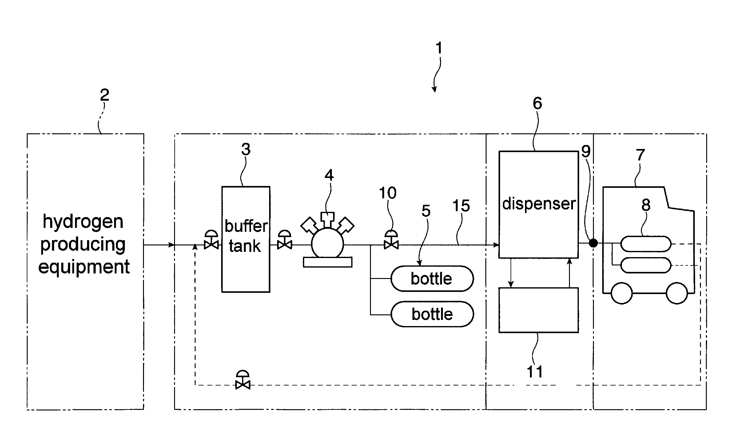
[0043]Embodiments of the present invention will be explained referring to figures below. FIG. 1 is a view of a constitution showing summary of a hydrogen filling system 1 embodiment. Hydrogen is produced with a known hydrogen producing equipment 2 and stored in a buffer tank 3 as a hydrogen storing tank. The hydrogen in this buffer tank 3 is supplied to a compressor 4 through piping, valves or the like and compressed with this compressor 4 to get high pressure. The hydrogen compressed to high pressure is stored in a hydraulic accumulator 5. The accumulator 5 consists of plurality of bottles and necessitated quantity of hydrogen can be taken out continuously through switching the valves of the these bottles sequentially. The hydrogen volume and pressure within each bottle, flow rate of hydrogen or the like are displayed on the display (not shown) provided in the hydrogen filling system.

[0044]In an ordinary manner, hydrogen produced with the hydrogen producing equipment 2 is transport...


PUM

PropertyMeasurementUnit
Pressureaaaaaaaaaa
Pressureaaaaaaaaaa
Electrical resistanceaaaaaaaaaa

Abstract

This invention has its aim in providing a hydrogen heat exchanger for a hydrogen filling system which is of a small size and has high heat transfer performance. The hydrogen filling system, in which a hydrogen tank (8) in a hydrogen fuel-cell automobile (7) is filled with pressurized hydrogen from a hydraulic accumulator (5), has a precooling apparatus (11) equipped with a heat exchanger (12) for cooling hydrogen to be filled. In the heat exchanger (12), the supply pressure in the hydrogen supplying channel (13) is substantially as high as the pressure in the coolant supplying channel (14). This allows the pipe wall of the intermediate pipe between both supplying channels to be thinner than in prior arts. Owing to this, heat transfer resistance and hydrogen pressure loss decrease, improving heat transfer performance and allowing the apparatus to be constituted in a small scale.

Description

FIELD OF THE INVENTION[0001]The present invention relates to a hydrogen heat exchanger for a hydrogen filling system. More specifically, the present invention relates to a hydrogen heat exchanger for a hydrogen filling system adapted for supplying cooled hydrogen into a hydrogen tank, for example, equipped in a hydrogen fuel-cell automobile.BACKGROUND OF THE INVENTION[0002]Automobiles utilizing hydrogen as fuel are known to be most ecological vehicles which do not generate carbon dioxide. It is necessary to establish hydrogen stations in place as needed, in a similar manner as gasoline stations supplying gasoline to automobiles with gasoline-engine, in order to supply hydrogen to the hydrogen tanks equipped in automobiles. Systems of various compositions have been proposed as ones which fill the hydrogen tanks with hydrogen in hydrogen stations.[0003]For example, a technique is known, in which hydrogen gas in a high pressure storing tank is introduced into a vortex tube to be separa...

Claims


Application Information

Patent Timeline
IPC IPC(8): B65B3/00
CPCF17C5/06F17C2270/0184F28D2021/0047Y02E60/321F17C2201/056F17C2205/0323F17C2205/0364F17C2205/037F17C2221/012F17C2223/0123F17C2225/0123F17C2225/035F17C2227/0135F17C2227/0157F17C2227/0341F17C2227/039F17C2250/01F17C2250/032F17C2250/043F17C2250/0439F17C2250/0443F17C2250/0694F17C2260/025F17C2260/026F17C2265/065F17C2270/0168F28D7/14Y02E60/32
Inventor TAKATA, YASUYUKIMURAKAMI, YUKITAKAWOODFIELD, PETER LLOYD
Owner NAT INST OF ADVANCED IND SCI & TECH
Why Eureka
Try Eureka