New energy automobile fuel cell system, working method, hydrogen inlet flow calculation method and efficiency evaluation method
What is Al technical title?
Al technical title is built by PatSnap Al team. It summarizes the technical point description of the patent document.
A fuel cell system and new energy vehicle technology, applied in fuel cells, electrical components, circuits, etc., can solve problems such as large power consumption, fuel cell output power drop, proton exchange membrane damage, etc., to improve utilization and reliability The effect of improving the performance and the reaction area
Active Publication Date: 2020-06-05
擎能动力科技(苏州)有限公司
View PDF14 Cites 24 Cited by
Summary
Abstract
Description
Claims
Application Information
AI Technical Summary
This helps you quickly interpret patents by identifying the three key elements:
Problems solved by technology
Method used
Benefits of technology
Problems solved by technology
[0003] In the air supply system, in order to increase the air density entering the fuel cell stack, the devices in the prior art use a centrifugal air compressor to pressurize the air (such as US2015380752A1, WO2014001253A1, US2010143810A1, JP2017010866A, KR20180092813A, etc.), but the compressed If the air temperature is too high, it does not meet the requirements of the temperature entering the fuel cell stack. If the temperature is too high, it will cause damage to the proton exchange membrane and reduce the output power of the fuel cell.
Since the normal operating temperature of the fuel cell stack is 50 to 100°C, it is necessary to use deionized cooling water to cool down the high-temperature gas compressed by the centrifugal air compressor, which not only consumes the power consumption of the cooling system but also causes a waste of energy, so how Using this part of energy to recover has become the direction of research; in the hydrogen supply system, hydrogen is a flammable gas and is mainly produced by electrolysis of water in industry, which will consume a large amount of electric energy, so in this device How to improve the utilization rate of hydrogen and ensure the reliability of the hydrogen supply system has become another focus of new energy vehicle fuel cells
Method used
Image
Click on the blue label to locate the original text in one second.
Reading with bidirectional positioning of images and text.
Examples
Embodiment 1
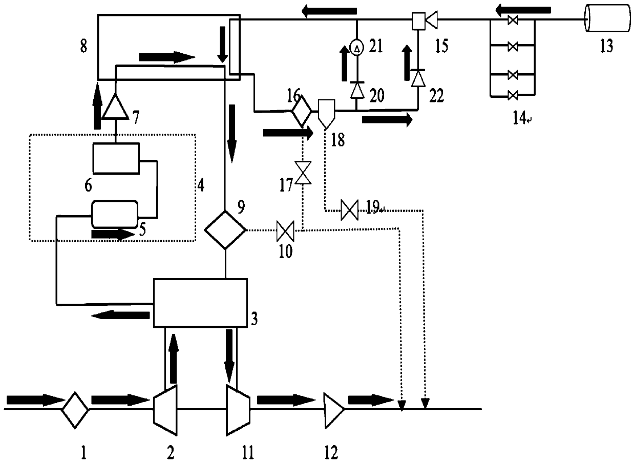
[0070] Embodiment one, such as figure 1 As shown, the invention consists of three parts: air supply system, hydrogen supply system and fuel cell stack;
[0071] The air supply system provides fresh air for the fuel cell stack;
[0072] The hydrogen supply system provides fresh hydrogen for the fuel cell stack;
[0073] The fuel cell stack is where the hydrogen and air react, converting chemical energy into electrical energy that provides kinetic energy to the appendages and loads.
[0074] Specifically, the fuel cell air supply system includes: air filter 1, centrifugal air compressor 2, gas heat exchanger 3, humidification intercooler assembly 4, throttle valve 7, water separator 9, drain valve 10 , turbine 11, back pressure valve 12. Wherein, the humidifying and intercooling assembly is composed of two parts, an intercooler 5 and a humidifier 6 .
[0075] Wherein, the air filter 1 can remove particulate impurities in the air.
[0076] Wherein, the centrifugal air compr...
PUM
Abstract
The invention discloses a new energy automobile fuel cell system, a working method, a hydrogen inlet flow calculation method and an efficiency evaluation method, Belongs to the technical field of newenergy. Keys points of the new energy automobile fuel cell system are that the new energy automobile fuel cell system comprises an air supply system, a hydrogen supply system and a fuel cell stack, wherein the air supply system provides fresh air for the fuel cell stack, and the system comprises an air filter, a centrifugal air compressor, a gas heat exchanger, a humidifying and intercooling assembly, a throttle valve, a water segregator, a drain valve, a turbine and a back pressure valve; the hydrogen supply system provides fresh hydrogen for the fuel cell stack and comprises a hydrogen tank,a pressure reducing valve, an ejector, a water distributor, a water distribution valve, a nitrogen discharger, a nitrogen discharge valve, a first one-way valve, a circulating pump and a second one-way valve; and the fuel cell stack is a place where hydrogen and air react, and chemical energy is converted into electric energy to provide kinetic energy for accessory mechanisms and loads. The invention aims to provide the new energy automobile fuel cell system, the working method, the hydrogen inlet flow calculation method and the efficiency evaluation method, the stability of the fuel cell isimproved, and the efficiency of the fuel cell is conveniently calculated and evaluated.
Description
technical field [0001] The invention relates to the technical field of new energy vehicles, in particular to a new energy vehicle fuel cell system, a working method, a hydrogen intake flow calculation method, and an efficiency evaluation method. Background technique [0002] Fuel cells are devices that generate electricity through the chemical reaction of hydrogen and air. This process does not require combustion, so it is not limited by the Carnot cycle and the products are only water and heat, so it has attracted widespread attention. The air supply system and the hydrogen supply system are important components of the fuel cell, and they provide reactants for the fuel cell system. [0003] In the air supply system, in order to increase the air density entering the fuel cell stack, the devices in the prior art use a centrifugal air compressor to pressurize the air (such as US2015380752A1, WO2014001253A1, US2010143810A1, JP2017010866A, KR20180092813A, etc.), but the compress...
Claims
Application Information
Patent Timeline
Application Date:The date an application was filed.
Publication Date:The date a patent or application was officially published.
First Publication Date:The earliest publication date of a patent with the same application number.
Issue Date:Publication date of the patent grant document.
PCT Entry Date:The Entry date of PCT National Phase.
Estimated Expiry Date:The statutory expiry date of a patent right according to the Patent Law, and it is the longest term of protection that the patent right can achieve without the termination of the patent right due to other reasons(Term extension factor has been taken into account ).
Invalid Date:Actual expiry date is based on effective date or publication date of legal transaction data of invalid patent.