Nanocomposite thermoelectric conversion material and method of producing the same

a thermoelectric conversion material and nanocomposite technology, applied in the direction of non-metal conductors, conductors, organic conductors, etc., can solve the problems of inability to further increase the roughness of the interface, the need for further reduction of thermal conductivity, etc., to achieve the effect of increasing thermoelectric conversion performance, reducing thermal conductivity, and being a new structur

Inactive Publication Date: 2012-08-30
TOYOTA JIDOSHA KK
View PDF3 Cites 4 Cited by
  • Summary
  • Abstract
  • Description
  • Claims
  • Application Information

AI Technical Summary

Benefits of technology

[0013]The invention provides a nanocomposite thermoelectric conversion material that has a novel structure in which interface roughness between a matrix made of a thermoelectric conversion mate

Problems solved by technology

However, the thermal conductivity is required to be further decreased.
In

Method used


Image

  • Nanocomposite thermoelectric conversion material and method of producing the same
  • Nanocomposite thermoelectric conversion material and method of producing the same
  • Nanocomposite thermoelectric conversion material and method of producing the same

Examples


first example

[0058]A nanocomposite thermoelectric conversion material described below was produced using the first production method according to the invention.

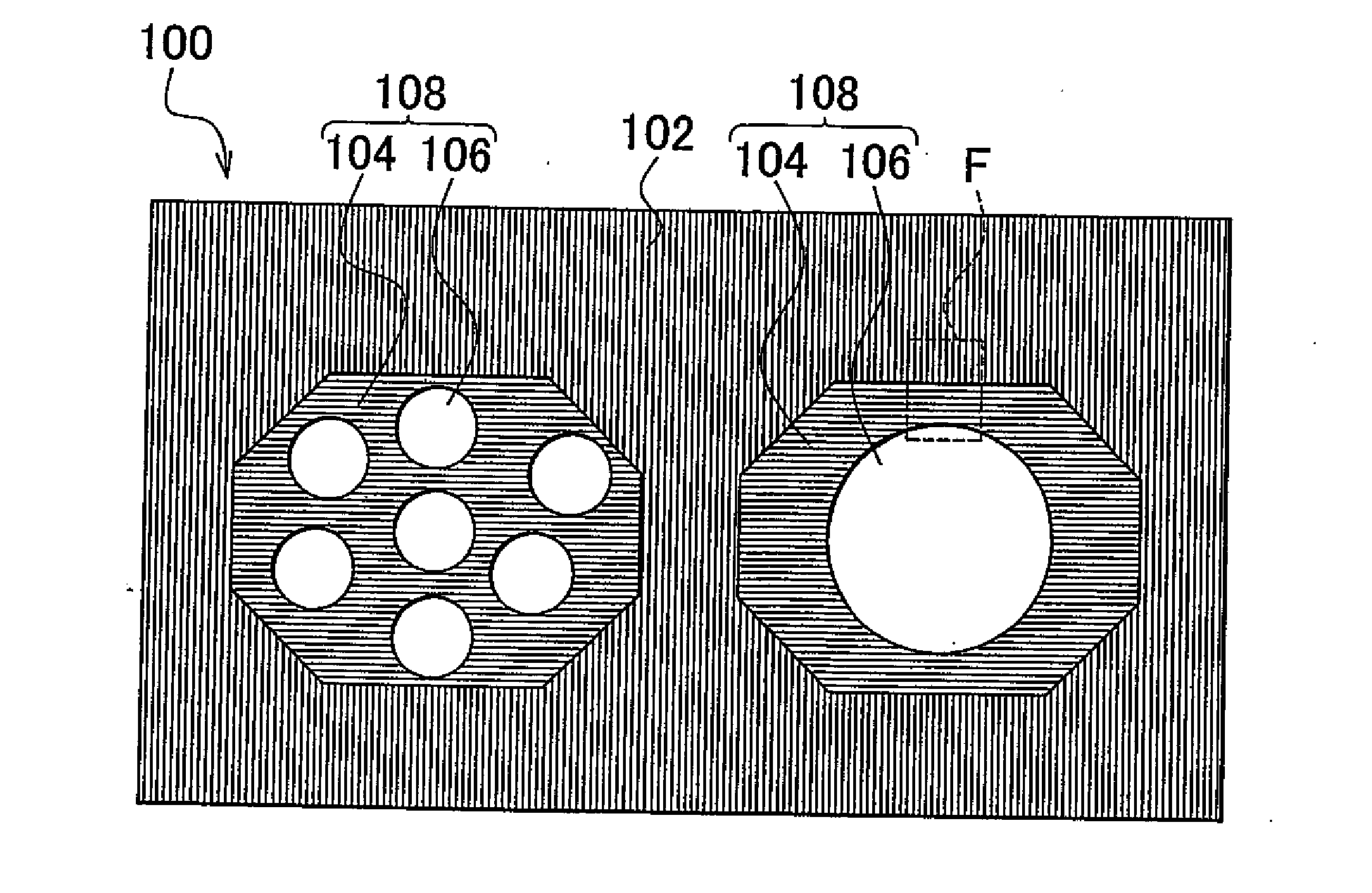
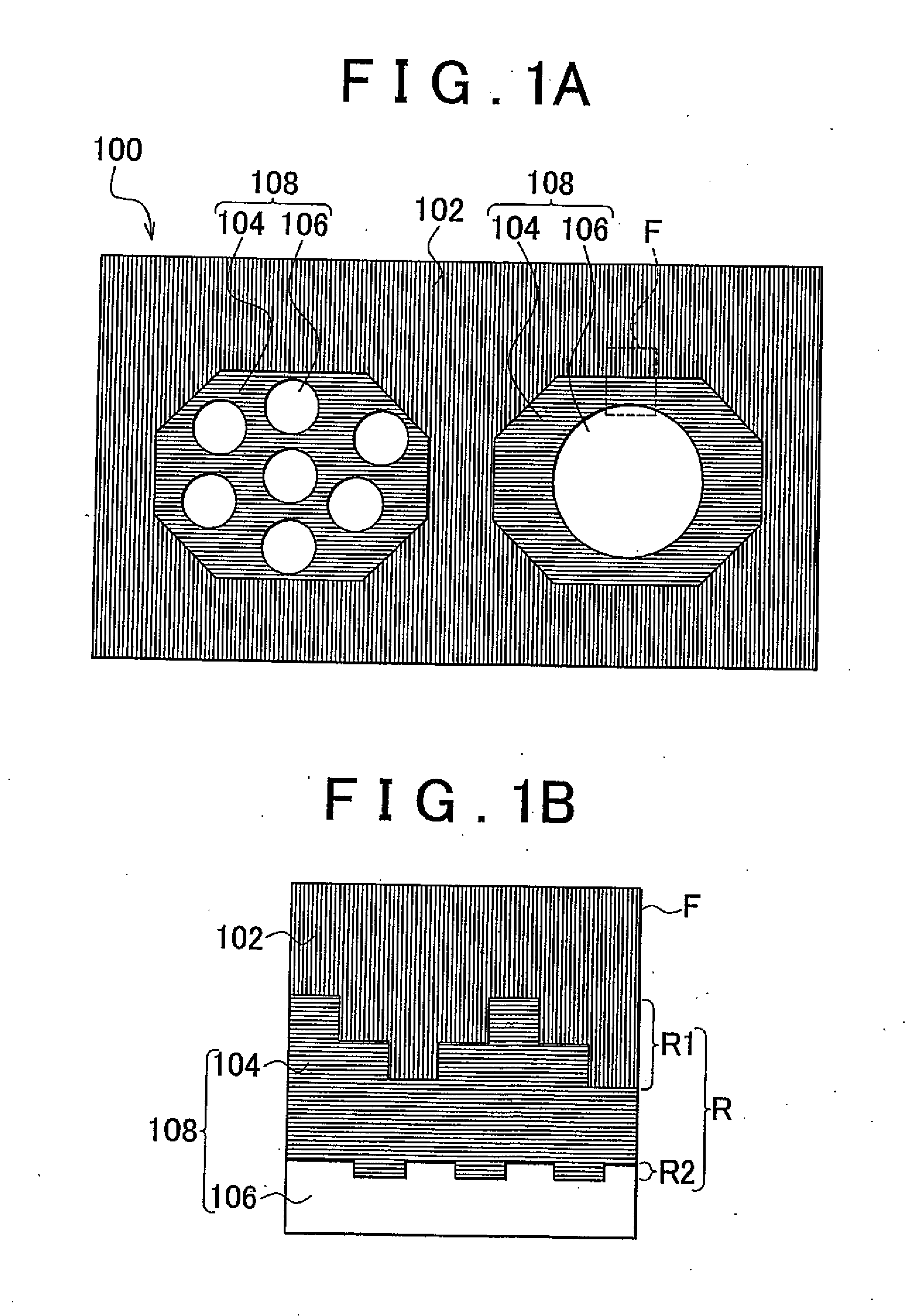
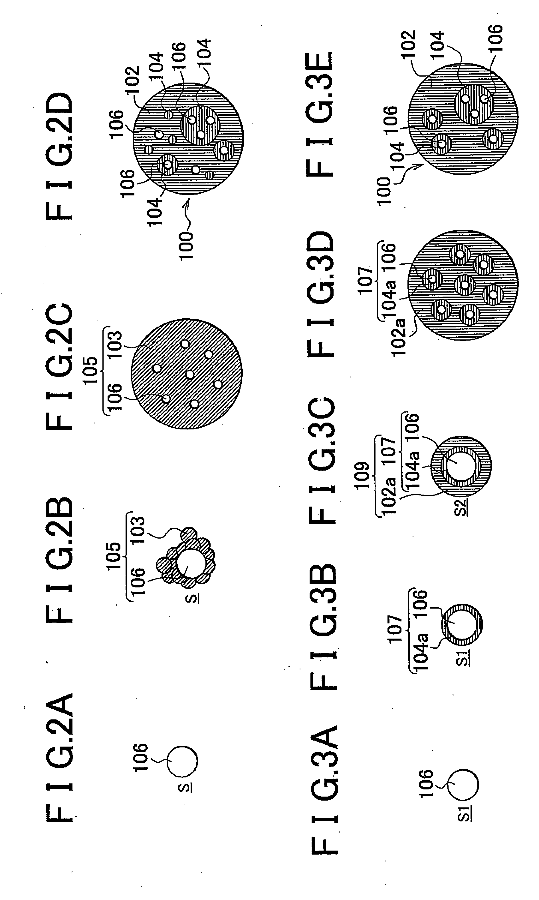
[0059]The configuration of the produced nanocomposite thermoelectric conversion material is as follows. A matrix was (Bi, Sb)2Te3. Amorphous particles were SiO2. Amorphous films were Sb2O3.

[0060]First Step

[0061]0.28 g of silica (SiO2) particles whose average diameter was 5 nm were dispersed in a solution produced by dissolving 0.4 g of bismuth chloride (BiCl3), 2.56 g of tellurium chloride (TeCl4), and 1.34 g of antimony chloride (SbCl3) in 100 ml of ethanol.

[0062]Second Step

[0063]Reduction was caused by dropping, into the above-described solution, a reducing agent produced by dissolving 2.5 g of NaBH4 in 100 ml of ethanol. Thus, ethanol slurry was produced. In the ethanol slurry, nanoparticles of silica (SiO2) were dispersed in the matrix-precursor made of the thermoelectric conversion material whose composition was (Bi, Sb)2Te3, and whi...

second example

[0075]The nanocomposite thermoelectric conversion material with the same configuration as the configuration of the nanocomposite thermoelectric conversion material in the first example was produced using the second production method according to the invention.

[0076]First Step

[0077]0.15 g of silica (SiO2) particles whose average diameter was 5 nm were dispersed in the first solution S1 produced by dissolving 0.32 g of antimony chloride (SbCL3) in 100 ml of ethanol.

[0078]Second Step

[0079]Reduction was caused by dropping, into the above-described first solution S1, a reducing agent produced by dissolving 0.6 g of NaBH4 in 100 ml of ethanol. As a result, Sb was precipitated on the surfaces of the silica (SiO2) nanoparticles to produce the films, and thus, the first nanocomposite particles were produced. The amounts of the first solution S1 and the reducing agent were adjusted so that the thickness of the Sb films became several nm.

[0080]Third Step

[0081]The first nanocomposite particles ...


PUM


Abstract

A nanocomposite thermoelectric conversion material (100) includes a crystalline matrix (102) made of a thermoelectric conversion material; and phonon-scattering particles (108) dispersed in the crystalline matrix (102). Each phonon-scattering particle (108) includes at least one amorphous nanoparticle (106) coated with a crystalline film (104) having a nano-order thickness, and the crystalline structure of the crystalline film (104) is different from the crystalline structure of the thermoelectric conversion material. The nanocomposite thermoelectric conversion material (100) is produced by i) precipitating a matrix-precursor oversaturated with one element of the thermoelectric conversion material, around the amorphous nanoparticles, thereby producing nanocomposite particles, and heat-treating the nanocomposite particles, or ii) by precipitating only one element of the thermoelectric conversion material around the amorphous nanoparticles, thereby producing first nanocomposite particles, and then, precipitating the matrix-precursor made of the thermoelectric conversion material, around the first nanocomposite particles, thereby producing second nano composite particles, and heat-treating the second nanocomposite particles.

Description

BACKGROUND OF THE INVENTION[0001]1. Field of the Invention[0002]The invention relates to a nanocomposite thermoelectric conversion material in which nano-sized phonon-scattering particles are dispersed in a matrix made of a thermoelectric conversion material, and a method of producing the same.[0003]2. Description of the Related Art[0004]A thermoelectric conversion material is an energy material that directly converts thermal energy to electric energy, based on two basic thermoelectric effects, that is, the Seebeck effect and the Peltier effect.[0005]A thermoelectric generation device, which uses the thermoelectric conversion material, has many advantages as compared to conventional power generation technologies. For example, the thermoelectric generation device has a simple structure, and is robust and highly durable. The thermoelectric generation device does not have a movable member. The micro-sized thermoelectric generation device is easily produced. The thermoelectric generatio...

Claims


Application Information

Patent Timeline
IPC IPC(8): H01B1/00B82Y30/00B82Y40/00
CPCH01L35/16H01L35/26Y10S977/833H01L33/26H01L33/16H10N10/852H10N10/857
Inventor MURAI, JUNYAKITA, TAKUJI
Owner TOYOTA JIDOSHA KK
Why Eureka
Try Eureka