Brushless pm machine construction enabling low coercivity magnets

a permanent magnet, low coercivity technology, applied in the manufacture of stator/rotor bodies, solid insulation, transportation and packaging, etc., can solve the problems of high-power machines that cannot be used, materials that are not currently adopted, and volatile prices of rare earth materials, etc., to achieve low coercivity, high performance, and demagnetization potential

Active Publication Date: 2012-08-30
DANFOSS POWER SOLUTIONS US CO
View PDF10 Cites 34 Cited by
  • Summary
  • Abstract
  • Description
  • Claims
  • Application Information

AI Technical Summary

Benefits of technology

[0004]Exemplary embodiments of the present disclosure provide a permanent magnet machine with the properties of rare earth machines, without utilizing the rare earth materials. For instance, exemplary embodiments of the present disclosure provide a PM machine architecture which can deliver high performance without the use of rare earth permanent magnets. The exemplary PM machine architecture includes a rotor geometry that allows the use of lower energy magnet material, such as AlNiCo and FeCoW, for example. These magnetic materials are not currently adopted because of low coercivity when compared to rare earth magnets. This translates into the potential for demagnetization in high power machines, and the material is unusable in current machines due to this limitation. However, the exemplary PM machine architecture of the present disclosure includes a unique geometrical arrangement that keeps the operating flux of these magnets at a higher flux density than any other known architecture. By operating near the peak flux density of these magnets (e.g., the residual induction), low coercivity becomes acceptable.

Problems solved by technology

However, the price of rare-earth materials has proven to be volatile, leading to a desire for alternatives to these materials.
These magnetic materials are not currently adopted because of low coercivity when compared to rare earth magnets.
This translates into the potential for demagnetization in high power machines, and the material is unusable in current machines due to this limitation.

Method used


Image

  • Brushless pm machine construction enabling low coercivity magnets
  • Brushless pm machine construction enabling low coercivity magnets
  • Brushless pm machine construction enabling low coercivity magnets

Examples


Embodiment Construction

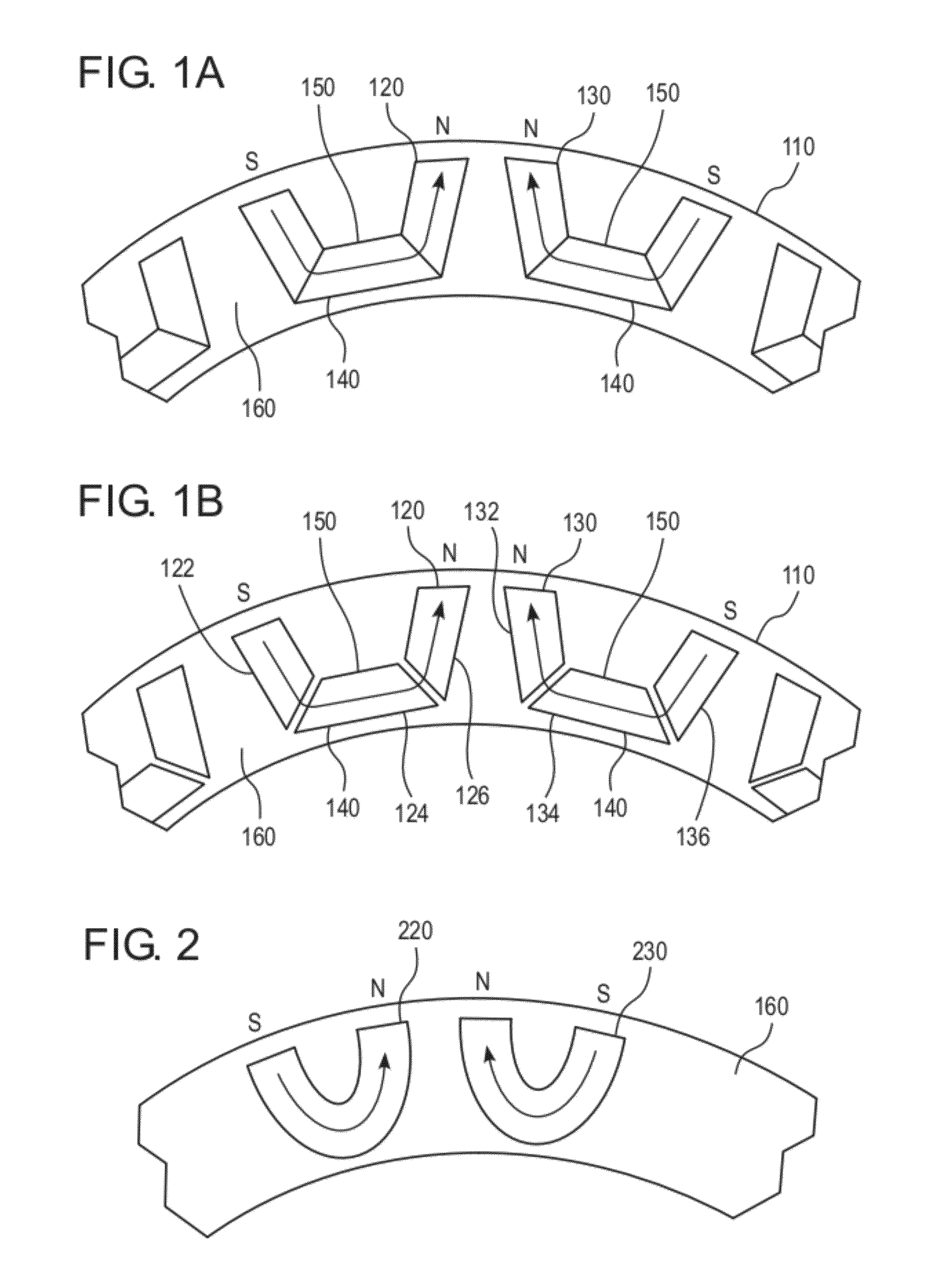
[0020]FIG. 1A illustrates a fragmentary cross-sectional view of a PM machine construction according to an exemplary embodiment of the present disclosure. FIG. 1A contains a partial view of a permanent magnet rotor 110 (rotor core) that is rotatably mounted on a motor shaft. The permanent magnet rotor 210 is essentially circularly shaped. The motor shaft is arranged inside of the inner circumference of the rotor 110, and a stator is arranged around or in proximity to the outer circumference of the rotor 110. The motor shaft and stator are known and are therefore not illustrated.

[0021]The fragmentary view of FIG. 1A illustrates a pair of magnets 120, 130 arranged in the rotor 110. According to an exemplary embodiment, a plurality of pairs of magnets 120, 130 extend throughout the rotor core 110, such that a plurality of pairs of magnets 120, 130 are contained throughout the essentially circular shape of the rotor 110. In the exemplary embodiment illustrated in FIG. 1A, the pair of mag...


PUM

PropertyMeasurementUnit
thicknessaaaaaaaaaa
coercivityaaaaaaaaaa
magnetizationaaaaaaaaaa

Abstract

The present disclosure provides a brushless permanent magnet machine which includes an essentially circular shaped rotor, and a pair of magnets arranged in the rotor. The magnets are each U-shaped and have a thickness direction extending along a contour of the corresponding magnet between the opposite poles of the corresponding magnet, respectively. The magnets are each composed of a non-rare earth material having a lower coercivity than a rare earth material. A direction of magnetization of each of the pair of magnets is parallel to the thickness direction of the corresponding magnet. The present disclosure also provides a method of manufacturing such a brushless permanent magnet machine.

Description

RELATED APPLICATION[0001]This application claims the benefit under 35 U.S.C. §119 of U.S. Provisional Patent No. 61 / 447,280 filed on Feb. 28, 2011, the entire contents of which are hereby incorporated by reference in their entireties.FIELD[0002]The present disclosure relates to the field of brushless machine architectures. More particularly, the present disclosure relates to an architecture or construction of a brushless permanent magnet (PM) machine or PM synchronous machine that enables the use of low coercivity magnets, such as Aluminum Nickel Cobalt (AlNiCo) or Iron Cobalt Tungsten (FeCoW), for example.BACKGROUND INFORMATION[0003]Induction machines and wound-field machines are two types of high power propulsion technologies that do not rely upon rare earth magnets. Both technologies consume power to create their magnetic fields and both have, to date, been bypassed in favor of permanent magnet machines (e.g., the hybrid automobiles built by Toyota®, Honda®, GM®, Ford® and Chrysl...

Claims


Application Information

Patent Timeline
Patent Type & Authority Applications(United States)
IPC IPC(8): H02K21/12H02K15/03
CPCH02K1/2753Y10T29/49012H02K1/2766Y02T10/64
Inventor LUTZ, JONLEY, JOSH
Owner DANFOSS POWER SOLUTIONS US CO
Why Eureka
Try Eureka