
Thermodynamic Machine and Method for the Operation Thereof

a technology of thermodynamic machines and cylinders, applied in mechanical equipment, machines/engines, steam engine plants, etc., can solve problems such as undesirable development of vapor bubbles

Active Publication Date: 2012-09-13
ORCAN ENERGY AG
View PDF7 Cites 18 Cited by
  • Summary
  • Abstract
  • Description
  • Claims
  • Application Information

AI Technical Summary

Benefits of technology

[0019]It is an object of the invention to develop a thermodynamic machine of the type referred to in the introduction to the effect that the occurrence of cavitation in the liquid or in the liquid working fluid is avoided as far as possible. It is furthermore an object of the invention to disclose a corresponding method for the operation of such a thermodynamic machine, wherein cavitation in the liquid is avoided as far as possible.
[0028]The invention, in certain embodiments, offers the distinct advantage in this respect that a compact thermodynamic machine for the utilization of low-temperature heat sources can be conceived. The installation space in this case is no longer necessarily predetermined by the necessary head height of the pump. Since basically the non-condensing auxiliary gas can be introduced on a one-off basis when filling the system, possibly even no constructional additional measures at all are required. In this respect, in certain embodiments, the invention offers an exceptionally inexpensive possibility for a further compacting of a thermodynamic machine. The invention, in certain embodiments, is extremely suitable in this respect for the conception of small mobile machines which are used for example on motor vehicles for the utilization of the engine heat, cooling medium heat or exhaust gas heat.
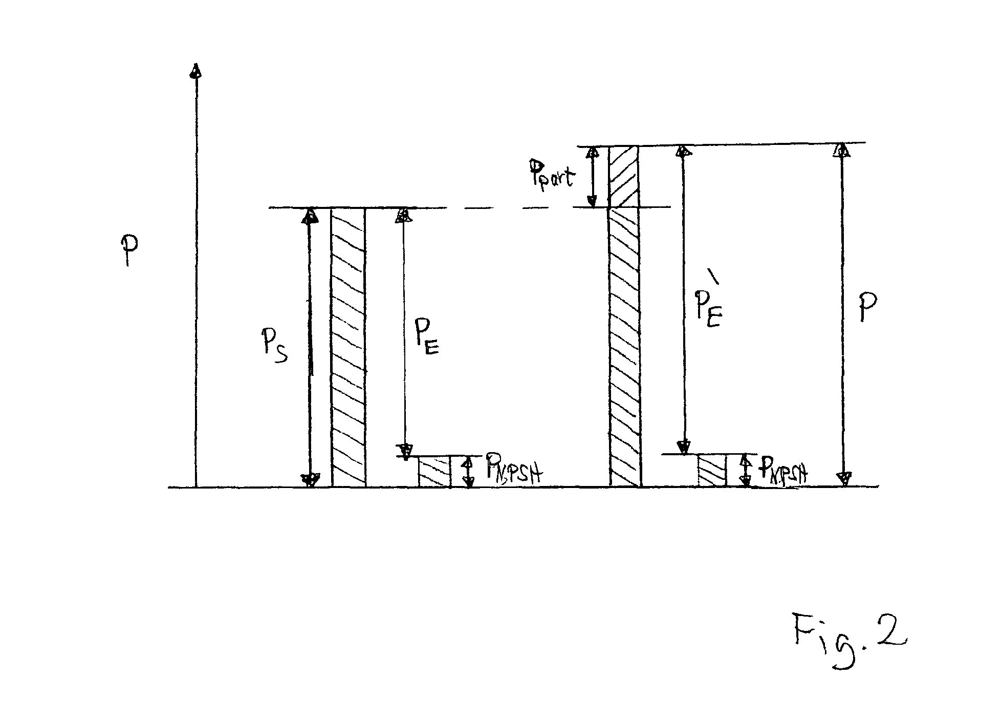
[0033]By means of an added non-condensing auxiliary gas (right-hand sub-figure of FIG. 2), a system pressure, which is the sum of the saturation vapor pressure ps and the partial pressure ppart of the auxiliary gas, results at the pump. After engaging the pump, this system pressure is again reduced by the suction pressure pNPSH which is predetermined by the NPSH value. If the partial pressure ppart of this non-condensing gas, which results on account of the introduced auxiliary gas, is greater than or at least equal to the suction pressure pNPSH at the suction connector of the pump, then the inlet pressure pE is now, however, at least equal to or greater than the saturation vapor pressure ps. Cavitation is therefore prevented.
[0037]The point of introduction for the auxiliary gas can be provided basically at any point of the cyclic system of the machine. The point of introduction can be designed in this case for an introduction on a one-off basis or for a repeated introduction of the auxiliary gas. In a preferred development, a point of introduction for the auxiliary gas is provided between the expansion machine and the liquid pump. In this way, the auxiliary gas is available directly at the required point in the cycle. The auxiliary gas is introduced into the liquid phase on the cold side of the cyclic process. In particular, the auxiliary gas can also be easily removed there since it can be collected in the condenser. To this end, for example the machine can be “cold-run”, as a result of which the auxiliary gas flows slowly into the condenser. For adding the auxiliary gas, a compressor, for example, can be used. Alternatively, a pressurized cylinder can be connected. Adding the auxiliary gas on the hot side of the cyclic process is associated with additional cost.
[0042]In order to avoid this disadvantage when a non-condensing auxiliary gas is being added, the condenser is advantageously designed for an entrainment of the auxiliary gas in the flow direction of the condensate or of the liquid working fluid. Such a condenser is designed for example as an air condenser or by means of plate-type heat exchange elements. In the case of an air condenser, the gaseous working fluid flows through the interior of tubes which on the outside are exposed to circumflow by air, for example, but also by another cooling medium. In this case, the auxiliary gas is pushed through the tubes in the flow direction at least partially by following gaseous working fluid. This also applies to condensers which are formed by means of plate-type heat exchange elements. Also in this case, the gaseous working fluid flows through the interspaces of the plate-type heat exchange elements and some of the auxiliary gas is taken from the condenser as well. The undesirable effect of the forming of an insulating layer which is produced for a shell-and-tube heat exchanger is lessened as a result of this.

Problems solved by technology

An undesirable development of vapor bubbles occurs.

Method used


Image

  • Thermodynamic Machine and Method for the Operation Thereof
  • Thermodynamic Machine and Method for the Operation Thereof
  • Thermodynamic Machine and Method for the Operation Thereof

Examples


Embodiment Construction

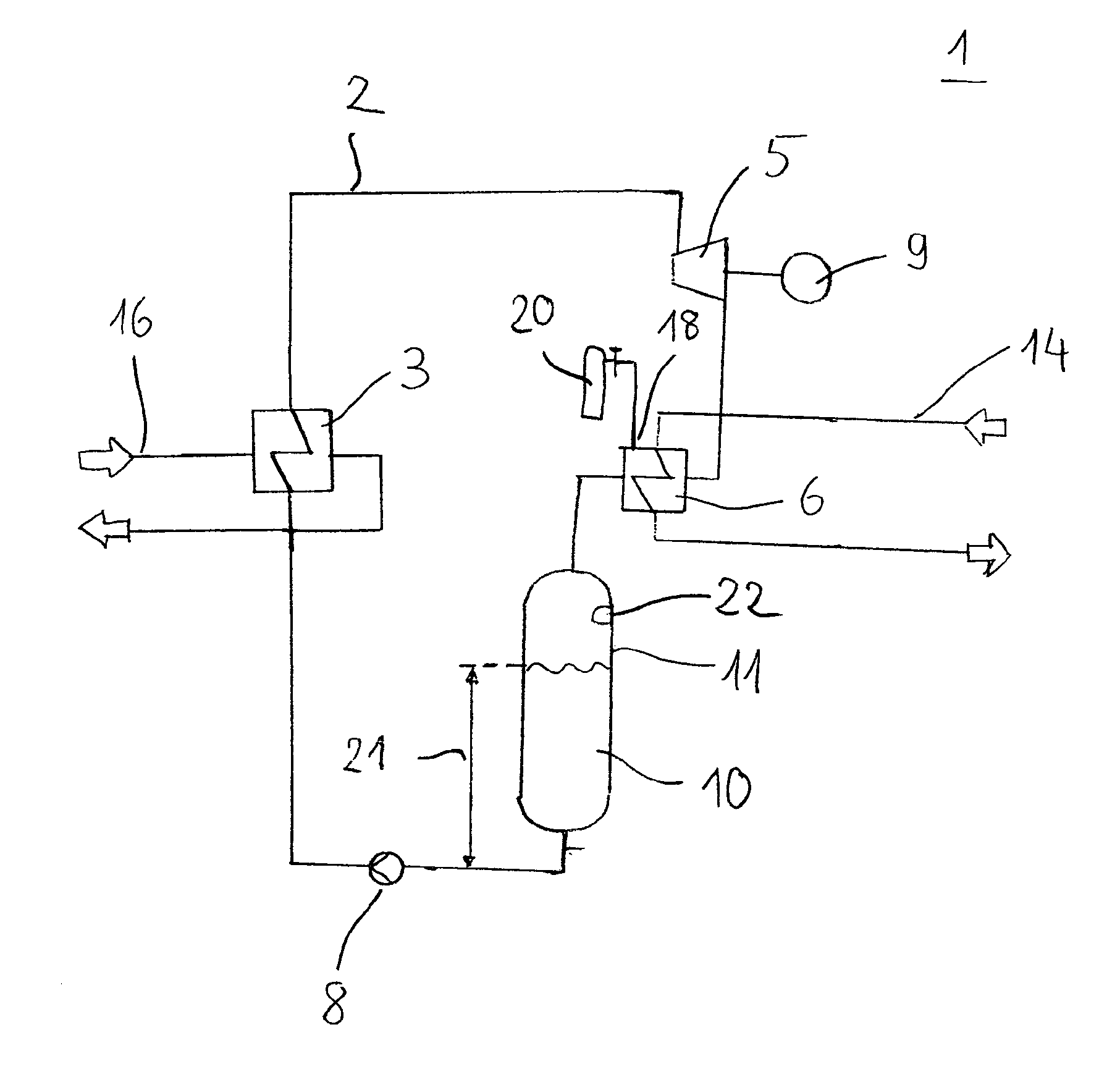
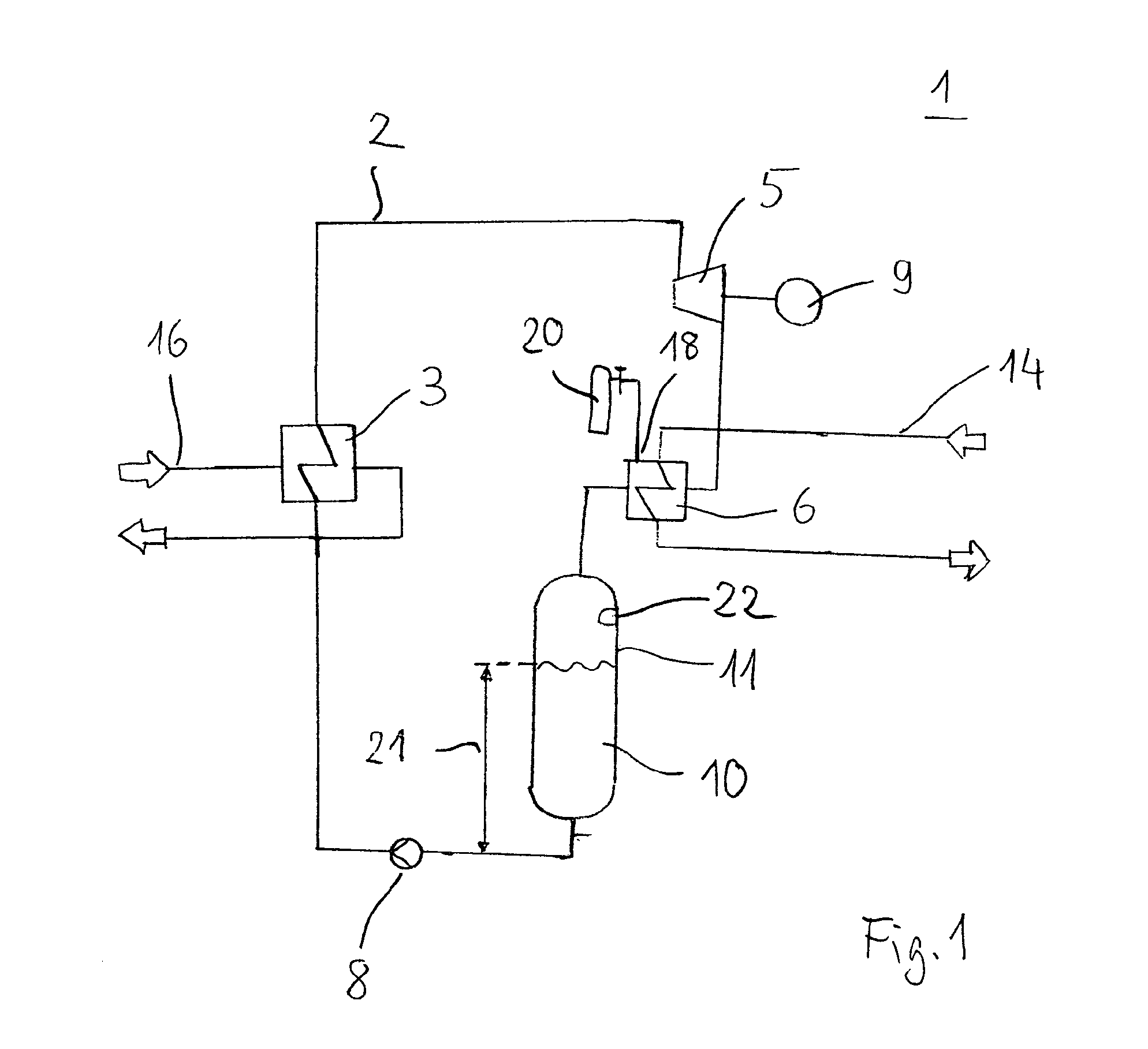
[0052]Schematically shown in FIG. 1 is an ORC machine 1, as is suitable particularly as a mobile plant for the utilization of waste heat of internal combustion engines. The ORC machine 1 comprises in this case—in a cyclic system 2—an evaporator as a heat exchanger 3, an expansion machine 5, a condenser 6 and a liquid pump 8. The depicted ORC machine 1 operates in accordance with the Rankine cyclic process, wherein work is performed on the expansion machine 5 for driving a generator 9. The generator 9 is designed particularly for feeding the generated power to the motor vehicle's own electric system, or is connected thereto. A hydrocarbon, which has a significantly higher vapor pressure compared with water, is used as working fluid 10. The working fluid 10 is located in a closed cycle.

[0053]The liquid working fluid 10 which is delivered via the liquid pump 8 is evaporated in the evaporator 3 at a high pressure. In the expansion machine 5, which is designed as a positive displacement ...


PUM


Abstract

The invention relates to a thermodynamic machine having a circulation system in which a working fluid, in particular a low-boiling working fluid, circulates alternately in a gaseous and a liquid phase, a heat exchanger, an expansion machine, a condenser, and a fluid pump. The invention also relates to a method for operating the thermodynamic machine. According to certain embodiments of the invention, in the flow line of the fluid pump, a partial pressure increasing the system pressure is applied to the liquid working fluid by adding a non-condensing auxiliary gas. Compact ORC machines can be implemented, preventing cavitation in the liquid working fluid.

Description

FIELD OF THE INVENTION[0001]The invention relates to a thermodynamic machine with a cyclic system, in which a particularly low-boiling working fluid circulates alternately in a gas phase and a liquid phase. In this case, the machine comprises a heat exchanger, an expansion machine, a condenser and a liquid pump. The invention additionally relates to a method for the operation of such a thermodynamic machine, wherein in a cycle the working fluid is heated, expanded, condensed and delivered by means of pumps of the liquid working fluid.BACKGROUND OF THE INVENTION[0002]Particularly a machine which operates in accordance with the thermodynamic Rankine cyclic process is understood by such a thermodynamic machine. The Rankine cyclic process in this case is characterized by pumping the liquid operating medium, by evaporating the operating medium at high pressure, by expanding the gaseous working fluid—performing mechanical work—and by condensing the gaseous working fluid at low pressure. M...

Claims


Application Information

Patent Timeline
IPC IPC(8): F01K25/08F01N5/02F01K13/00
CPCF01K15/02F01K25/08F01K23/065F01K21/04
Inventor SCHUSTER, ANDREASSICHERT, ANDREASAUMANN, RICHARD
Owner ORCAN ENERGY AG
Learn More