Non-linear resonating sensor and a method

a non-linear resonating sensor and sensor technology, applied in the field of non-linear resonating sensors and methods, can solve the problems of low cost of rfid tags, difficult wired readout, and large potential of wireless sensors, and achieve low cost and complexity of wiring, cost-effectively, and low mass production

Active Publication Date: 2012-09-20
TEKNOLOGIAN TUTKIMUSKESKUS VTT
View PDF8 Cites 19 Cited by
  • Summary
  • Abstract
  • Description
  • Claims
  • Application Information

AI Technical Summary

Benefits of technology

[0021]A sensor in accordance with embodiments of the present invention is well suited for applications where a wired readout is difficult, for example, due to harsh operating conditions, rotating parts or the cost and complexity of wiring. A potential application for sensers according to the present invention is within the field of temperature measurements in industrial machinery and engines. A ferroelectric varactor can be cost-effectively realized using thin-film manufacturing technologies and can be a solid-state device, which both can be advantageous, for example when compared to MEMS-based non-linear elements. Low-cost mass production of the entire sensor using the printed electronics manufacturing methods can also be achieved.
[0022]Furthermore, a sensor according to certain embodiments of the present invention can be exploited in applications where low-cost passive sensors are required, e.g., measuring moisture, strain or temperature in building structures. Also, such sensor solutions are well-suited for applications in harsh operating environments. Low-cost fabrication techniques, including but not limited to printed electronics methods, can be beneficial in enabling commercial viability.

Problems solved by technology

Wireless sensors have a great deal of potential in numerous applications where a wired readout is difficult, for example, due to harsh operating conditions, rotating parts or cost and complexity of wiring.
The cost of an RFID tag is low due to their high manufacturing volumes.
An additional sensor element further increases power consumption.
Therefore, RFID does not suit well for applications where a long distance or a high operation frequency is required.
In addition, a piezoelectric material as a sensing element may limit their applications.
However, these sensors can not be read across large distances as they require near-field coupling to the reader device.
Intermodulation sensors utilize mixing elements (a ferroelectric varactor and MEMS resonator) as sensing elements and do not facilitate a sensing element in a straightforward way.
In addition, proximity of dielectric or conductive material distorts the read-out of the ferroelectric intermodulation sensor.
Identification RFID tags are limited to small frequencies and relatively short read out distances and are not well-suited for harsh environments (high temperature etc.).
Typically they are also rather expensive (made on piezo-electric substrates).
Interrogation of resonance sensors requires a near-field coupling and these sensors are therefore limited to very short read-out distances.
These sensors also require more complex read-out technique as the coupling between the sensor and the read-out unit affects the sensor.

Method used


Image

  • Non-linear resonating sensor and a method
  • Non-linear resonating sensor and a method
  • Non-linear resonating sensor and a method

Examples


Embodiment Construction

Operation Principle of a Sensor According to an Embodiment of the Present Invention

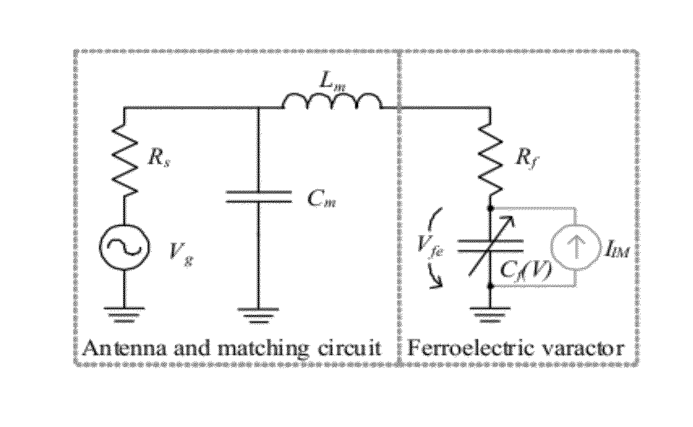
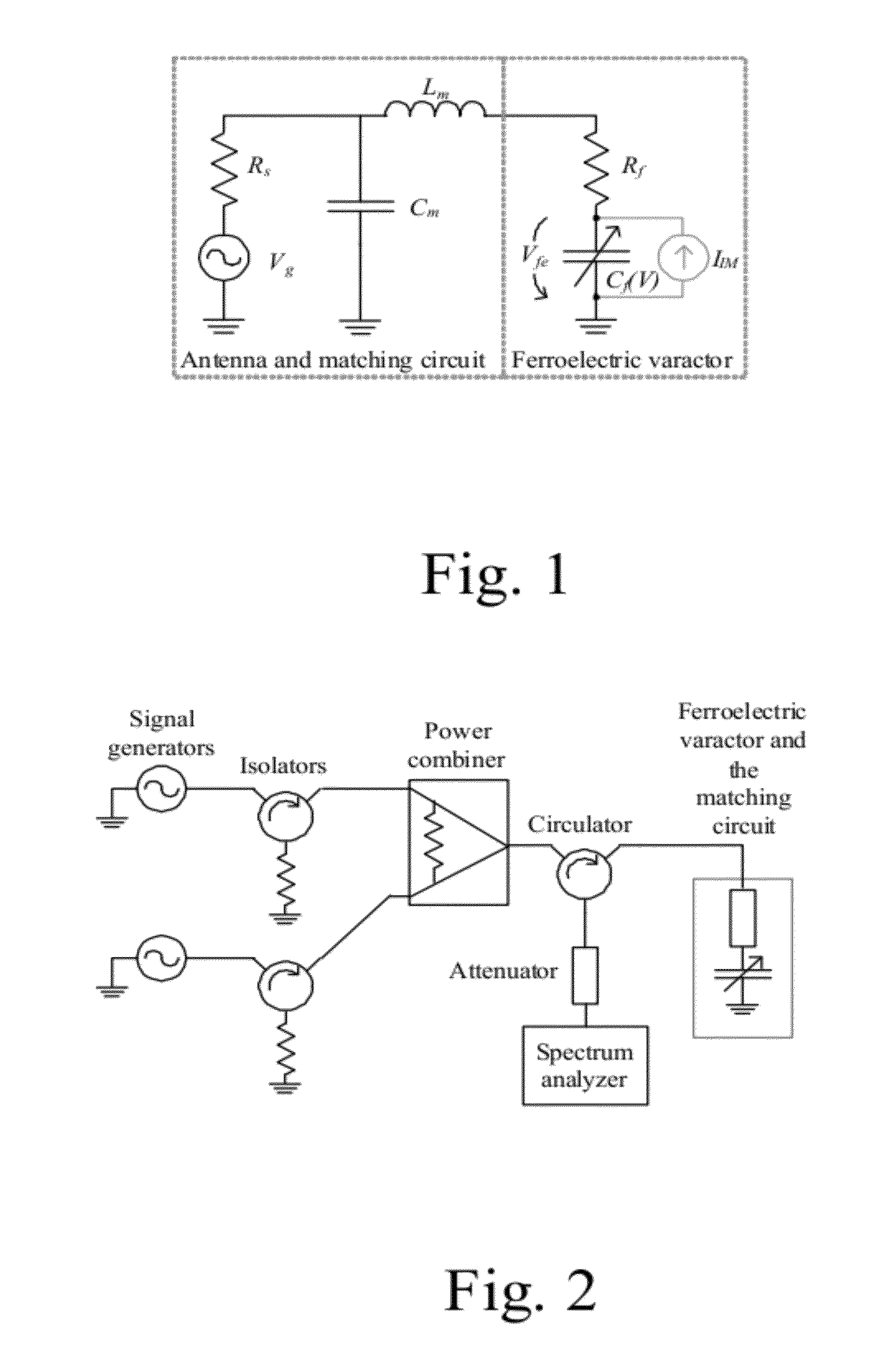
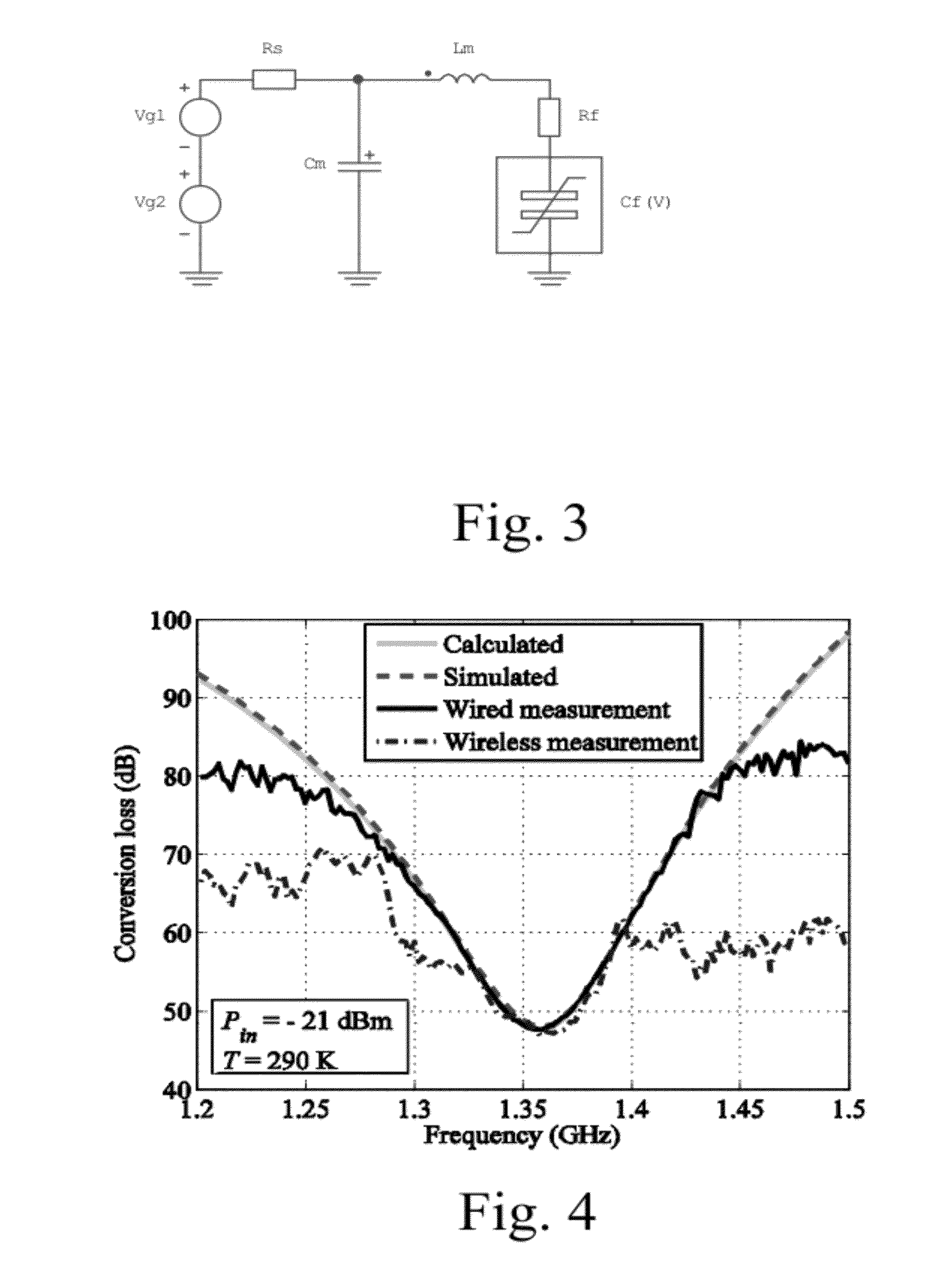
[0048]The sensor consists, or comprises of a ferroelectric varactor that is conjugate matched to an antenna. The equivalent electrical circuit of the sensor is shown in FIG. 1. The antenna is represented as an equivalent voltage source with the voltage Vg and the internal resistance Rs. The matching circuit consists, comprises, or comprises substantially of the shunt capacitance Cm and the series inductance Lm and may either be included into the antenna or it may be realized as a separate circuit. The resistance Rf represents the losses of the varactor and Cf (V) relates the non-linear capacitance to the voltage. The current source in parallel with the non-linear capacitance is used to represent the modulated current over the varactor in the following analysis.

[0049]The presented sensor can be realized using any non-linear element but the following analysis considers a Barium Strontium Titanate varact...


PUM


Abstract

Described herein is a passive wireless resonating non-linear sensor that is typically based on a ferroelectric varactor. The sensor replies its data at an intermodulation frequency when a reader device illuminates it at two closely-located frequencies. Furthermore, described herein is a general intermodulation read-out principle for passive wireless sensors. A sensor utilizes a mixing element, such as a varactor and it can be equipped with a capacitive, inductive, or resistive sensor element. When the sensor is illuminated with signals with two frequencies it replies the sensor data at an intermodulation frequency.

Description

[0001]The present application is a non-provisional application of provisional application 61 / 468,588 filed Mar. 29, 2011 which is herein incorporated by reference in its entirety.BACKGROUND OF THE INVENTION[0002]Wireless sensors have a great deal of potential in numerous applications where a wired readout is difficult, for example, due to harsh operating conditions, rotating parts or cost and complexity of wiring. Wireless sensors are passive, battery-assisted semi-passive, or active. The advantages of passive sensors are that their life-time or operation conditions are not limited by the battery and that they are inexpensive. Examples of passive wireless sensors are silicon-based radio frequency identification (RFID) tags, surface acoustic wave (SAW) RFID, and inductively-coupled resonance-circuit sensors.[0003]The RFID tags are based on integrated circuits (ICs), which enable several sophisticated features such as rewritable memory and anti-collision protocols. The cost of an RFID...

Claims


Application Information

Patent Timeline
Patent Type & Authority Applications(United States)
IPC IPC(8): G01S13/04H01Q15/00
CPCG06K19/0672G01S13/75
Inventor VIIKARI, VILLESEPPA, HEIKKIMATTILA, TOMIALASTALO, ARIALLEN, MARKVARPULA, TIMO
Owner TEKNOLOGIAN TUTKIMUSKESKUS VTT
Why Eureka
Try Eureka