Grating Based Optical Parametric Oscillator and Method of Dynamically Tuning the Oscillator for Generating Desired Optical Signals

a technology of optical parametric oscillator and oscillator, applied in the field of grating based optical parametric oscillator, can solve the problems of system impracticality for arbitrary chemical measurement, narrow linewidth is not conducive to optimum, and optimum measurement, and achieves the effect of effectively resonant within the cavity, quick tuning of the oscillator, and effective tuning of the resulting signal and idler wavelength

Active Publication Date: 2012-09-20
PERATON INC
View PDF3 Cites 9 Cited by
  • Summary
  • Abstract
  • Description
  • Claims
  • Application Information

AI Technical Summary

Benefits of technology

[0008]According to an embodiment of the present invention, an optical parametric oscillator (OPO) (e.g., for a laser transmitting device) includes a cavity with a plurality of optical components including non-linear optical media, optical beam manipulating elements, and a narrow linewidth filter in the form of a rotatable grating. The grating enables rapid tuning of the oscillator to provide an output beam with a desired wavelength. A pump laser provides a pump laser beam with a pump wavelength to the cavity, and the non-linear optical media convert the pump beam into light beams with a signal wavelength and an idler wavelength that are each longer than the pump wavelength. The signal and/or idler wavelengths serve as the desired waveleng...

Problems solved by technology

Further, these narrow linewidths are not conducive for optimum measurements since an extremely tight tolerance is mandated on the central wavelength.
However, this system is impractical for the ...

Method used


Image

  • Grating Based Optical Parametric Oscillator and Method of Dynamically Tuning the Oscillator for Generating Desired Optical Signals
  • Grating Based Optical Parametric Oscillator and Method of Dynamically Tuning the Oscillator for Generating Desired Optical Signals
  • Grating Based Optical Parametric Oscillator and Method of Dynamically Tuning the Oscillator for Generating Desired Optical Signals

Examples


Embodiment Construction

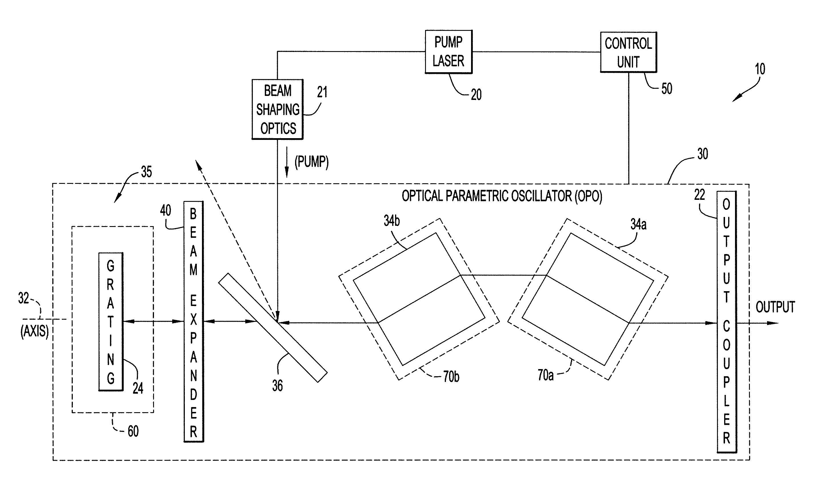
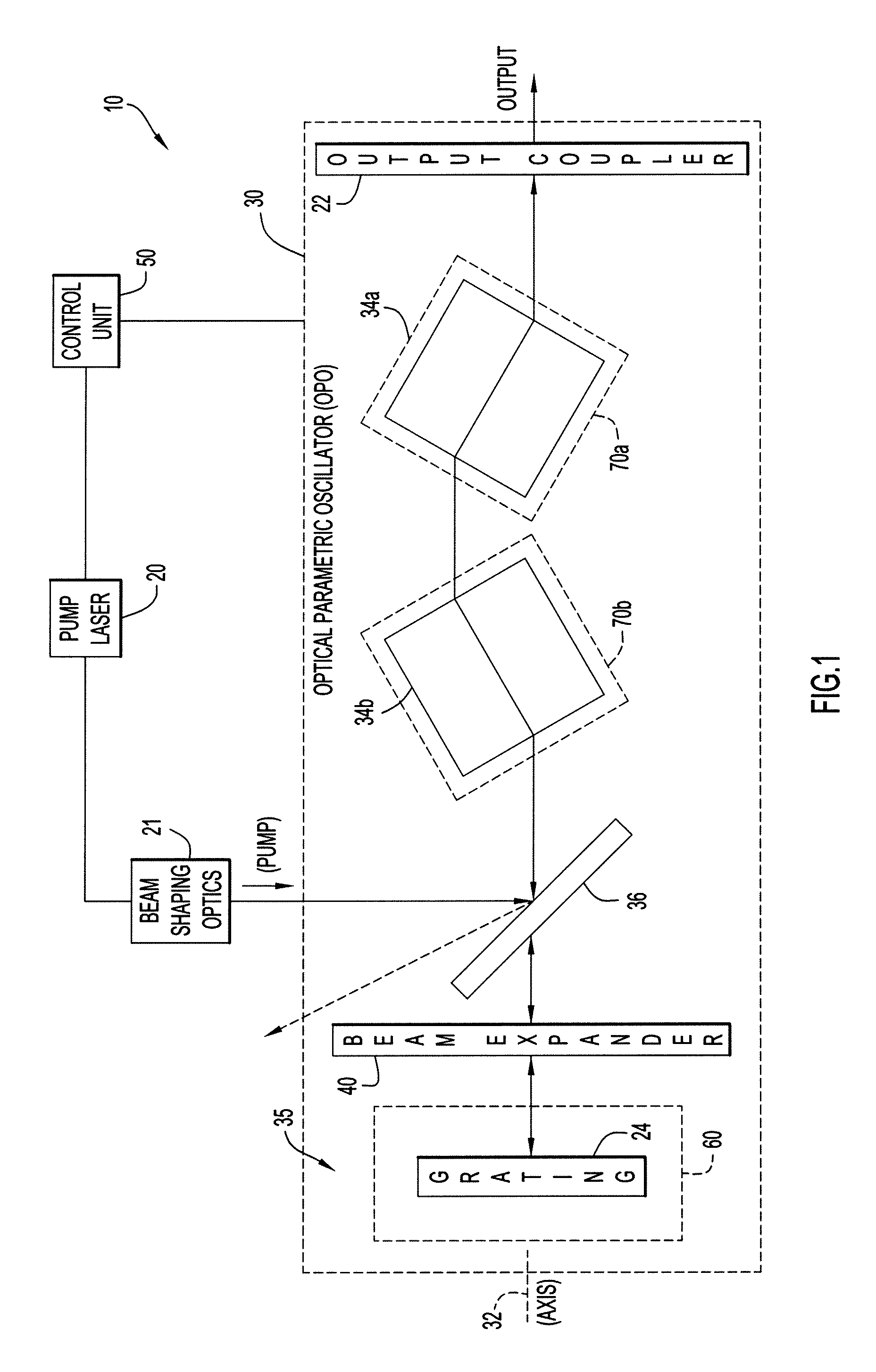
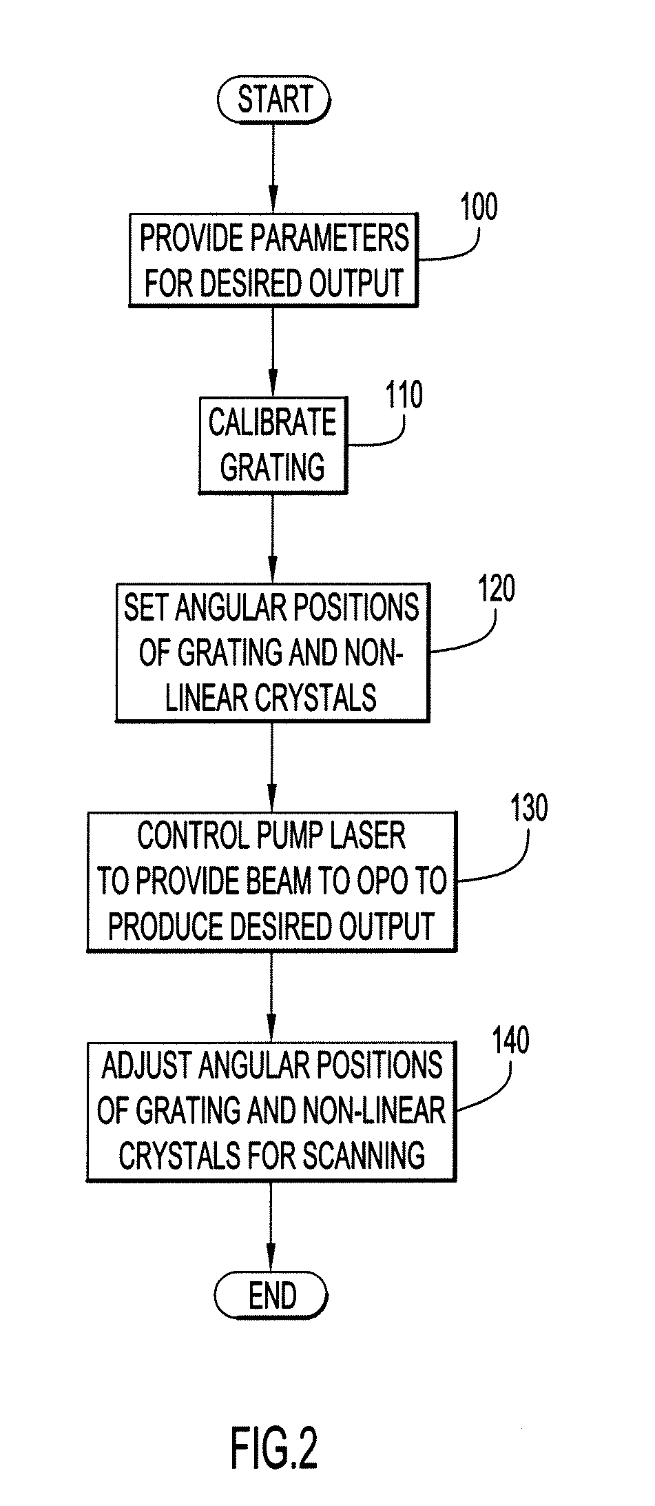
[0016]Present invention embodiments pertain to an optical parametric oscillator (OPO) providing a narrow linewidth (e.g., optical spectrum width or band) over a tunable wavelength range and enhanced power output. This enables the optical parametric oscillator (OPO) to be employed for detection of various chemicals (e.g., narrow-line and broad feature (or wider-line)) and / or biological aerosols. The optical parametric oscillator (OPO) includes a rotatable grating that enables rapid tuning of the oscillator. Since each angular orientation of the grating corresponds to a unique wavelength, deterministic and predictable tuning may be attained from sporadic calibration, and can be automated to provide customized sets of wavelengths for different applications, or alter the set of wavelengths during an application. In addition, alternative crystal materials (e.g., periodically poled lithium niobate (PPLN), rubidium titanyl arsenate (RTA), potassium titanyl arsenate (KTA), and the like each...


PUM


Abstract

According to an embodiment of the present invention, an optical parametric oscillator (OPO) (e.g., for a laser transmitting device) includes non-linear optical media, optical beam manipulating elements, and a narrow linewidth filter in the form of a rotatable grating. The grating enables rapid tuning of the oscillator to provide an output beam with a desired wavelength. A pump laser provides a pump laser beam, and the non-linear optical media convert the pump beam into light beams with a signal wavelength and an idler wavelength. The angular positions or orientations of the non-linear optical media relative to a longitudinal propagation axis of the optical parametric oscillator (OPO) are adjustable to effectively tune the resulting signal and idler wavelengths. An output coupler receives the resulting beams from the non-linear optical media, and emits beams with the desired wavelength (signal and/or idler wavelengths).

Description

BACKGROUND[0001]1. Technical Field[0002]The present invention embodiments pertain to devices producing optical signals. In particular, present invention embodiments pertain to an optical parametric oscillator (OPO) providing a narrow linewidth (e.g., optical spectrum width or band) over a tunable wavelength range and enhanced power output. The optical parametric oscillator (OPO) may be employed for detection of chemicals (e.g., narrow-line and broad feature (or wider-line)) and / or biological aerosols.[0003]2. Discussion of Related Art[0004]Optical parametric oscillators (OPO) are well-known, non-linear optical devices capable of producing coherent radiation at a desired frequency via parametric amplification. In a conventional optical parametric oscillator (OPO), a pump source supplies a beam of laser light at a pump wavelength to an optical cavity bounded by end mirrors and containing a non-linear optical medium (typically a non-linear optical crystal). As the pump beam propagates ...

Claims


Application Information

Patent Timeline
IPC IPC(8): G02F1/39
CPCG01N21/17G02F1/39G02F2203/58G02F2203/055G02F2203/15G02F2201/30
Inventor SHUMAN, TIMOTHY M.
Owner PERATON INC
Why Eureka
Try Eureka