
Angiography system for the angiographic examination of a patient and angiographic examination method

a technology for angiography and patient, applied in the field of angiography system, can solve the problems of new mask image creation, unfamiliar representation to the physician, etc., and achieve the effect of improving visibility in the vessel and simplifying the navigation of instruments

Active Publication Date: 2012-09-20
SIEMENS HEALTHCARE GMBH
View PDF6 Cites 26 Cited by
  • Summary
  • Abstract
  • Description
  • Claims
  • Application Information

AI Technical Summary

Benefits of technology

[0032]It has proven advantageous if the image regions lying within the segmentation are contrasted such that they are set to black in order to darken or homogenously color a specific offset value according to the local thickness of the vessel. Alternatively, the local thickness of the vessel can be calculated from the distances of the vessel edges detected by means of the segmentation or can be replaced, colored and / or darkened according to a mathematical forward projection of the segmentation (DRR).
[0035]It has proven advantageous for the apparatus for generating a mask image to effect a display of additional information, whereby this additional information can be displayed through recesses of mask parts.
[0049]The navigation of instruments is simplified by improved visibility in the vessel, if additional information is displayed in the mask image and / or the roadmap image. These can be displayed in accordance with the invention through recesses of mask parts, whereby the additional information is information relating to vascular courses, vascular occlusions, orifices and / or thrombi.

Problems solved by technology

The problem is that a new mask image has to be created for each new angulation.
This representation may however be unfamiliar to the physician.

Method used


Image

  • Angiography system for the angiographic examination of a patient and angiographic examination method
  • Angiography system for the angiographic examination of a patient and angiographic examination method
  • Angiography system for the angiographic examination of a patient and angiographic examination method

Examples


Embodiment Construction

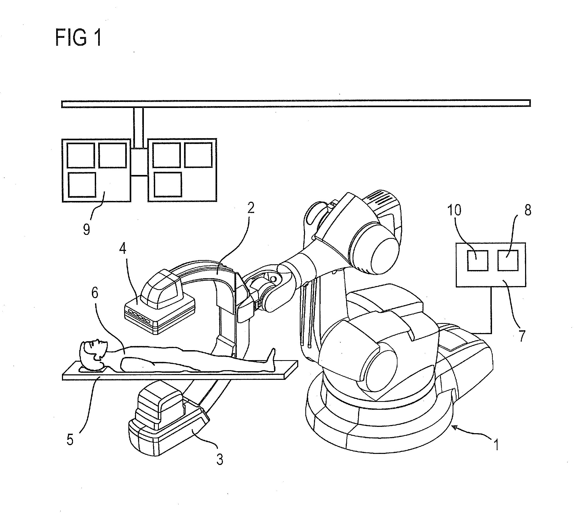
[0065]An abdominal aorta 11 is shown in FIG. 2, which comprises an abdominal aortic aneurysm (AAA). An abdominal aortic aneurysm (AAA) 12 is an aneurysm on the abdominal aorta 11.

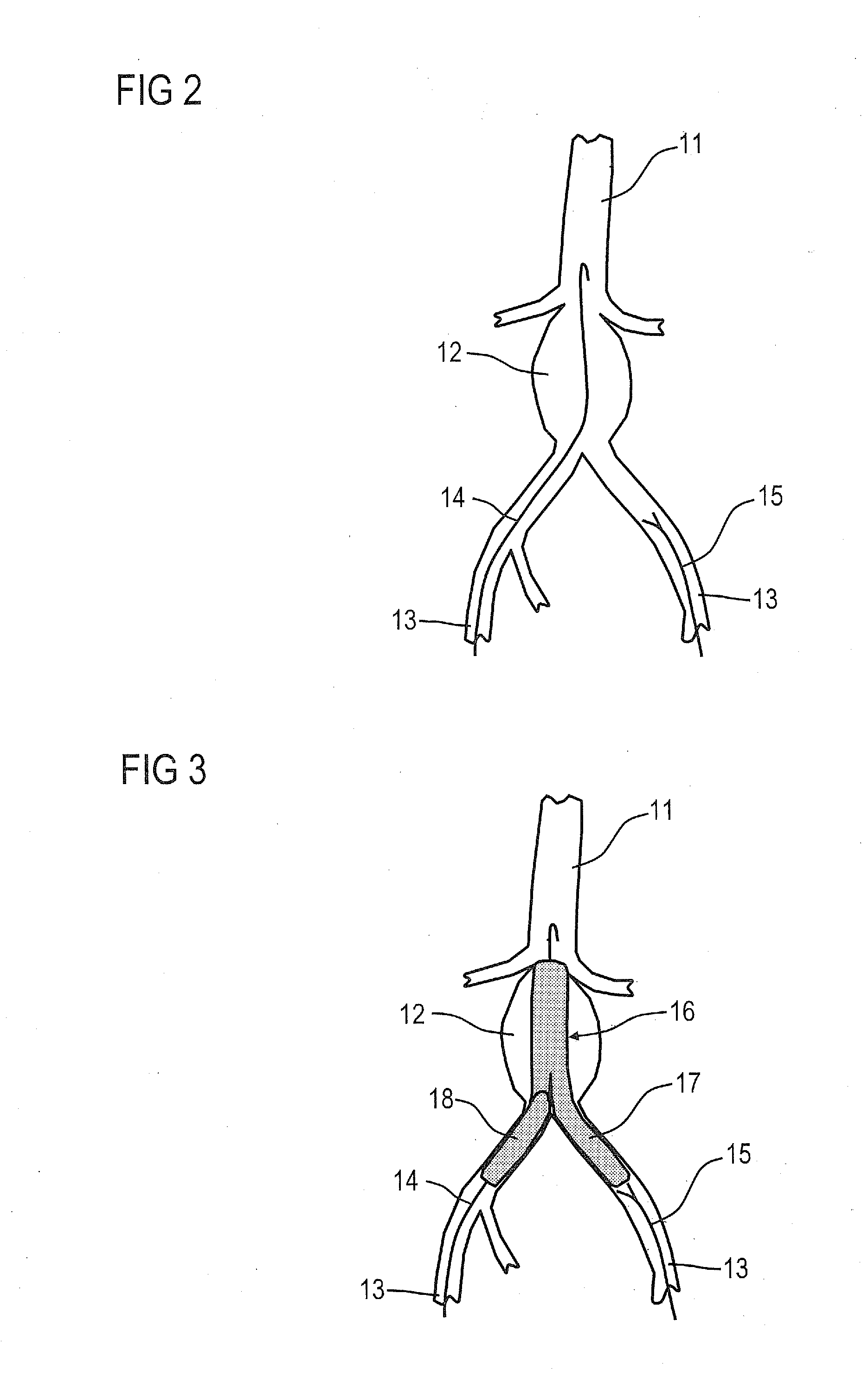
[0066]The aortic aneurysm 12 is treated by inserting a stent graft, in other words a composite stent graft device, such as is shown in FIG. 3. To this end, guide wires 14 and catheters 15 are introduced into the aorta 11 by way of the two strips through the leg arteries 13, by way of which the stent grafts 16 are introduced.

[0067]With complex stent grafts 16, which include the leg arteries 13, the final stent must sometimes be composed of “partial stents”, whereby a partial stent 18 for the other leg artery 13 is “flanged” on an aortic stent 17 for instance, which protrudes through the AAA into one of the leg arteries 13, through a so-called window.

[0068]The principle behind road mapping technology is now indicated in FIGS. 4 to 6 with the aid of a schematic representation. The basic idea behind the road ma...


PUM


Abstract

An angiography system for angiographic examination of a patient is provided. The system has an x-ray emitter and an x-ray image detector attached to the ends of a C-arm, a patient support couch, a system control unit, an image system and a monitor. The system control unit generates a mask image that detects a reference image, effects a registration of the reference image to the C-arm, whereby if necessary a segmentation of the examination object is implemented in the reference image, contrasts image regions lying inside of the segmentation in order to generate a mask image, and subtracts the mask image from fluoroscopy live images acquired by the angiography system without contrast agent in order to form a roadmap image. The image system effects a reproduction of the roadmap images on the monitor.

Description

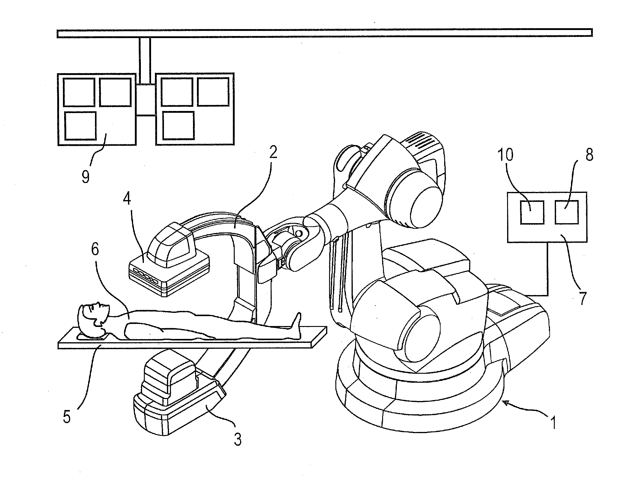
CROSS REFERENCE TO RELATED APPLICATIONS[0001]This application claims priority of German application No. 10 2011 005 777.3 filed Mar. 18, 2011, which is incorporated by reference herein in its entirety.FIELD OF INVENTION[0002]The invention relates to an angiography system for the angiographic examination or intervention of an organ, vascular system or other body regions as an examination object of a patient using an x-ray emitter, an x-ray image detector, which are attached to the ends of a C-arm, a patient support couch with a couch plate for supporting the patient, a system control unit, an imaging system and a monitor as well as an angiographic examination method for the angiography system.BACKGROUND OF INVENTION[0003]An angiography system of this type is known for instance from U.S. Pat. No. 7,500,784 B2 which is explained with the aid of FIG. 1.[0004]FIG. 1 shows a monoplanar x-ray system shown as an example having a C-arm 2 held by a stand 1 in the form of a six-axle industrial...

Claims


Application Information

Patent Timeline
Patent Type & Authority Applications(United States)
IPC IPC(8): A61B6/03G06K9/00A61B6/00
CPCA61B6/0407A61B6/12A61B6/4441A61B6/4458A61B6/487A61B6/504A61B6/5235A61B6/481
Inventor PFISTER, MARCUS
Owner SIEMENS HEALTHCARE GMBH
Learn More