

Method of depositing zinc oxide coatings by chemical vapor deposition
a technology zinc oxide coating, which is applied in the direction of chemical vapor deposition coating, coating, metallic material coating process, etc., can solve the problems of significantly more expensive production of sputtered films, and achieve the effect of increasing the laminarity of each stream
- Summary
- Abstract
- Description
- Claims
- Application Information
AI Technical Summary
Benefits of technology
Problems solved by technology
Method used
Image

Examples
example 2
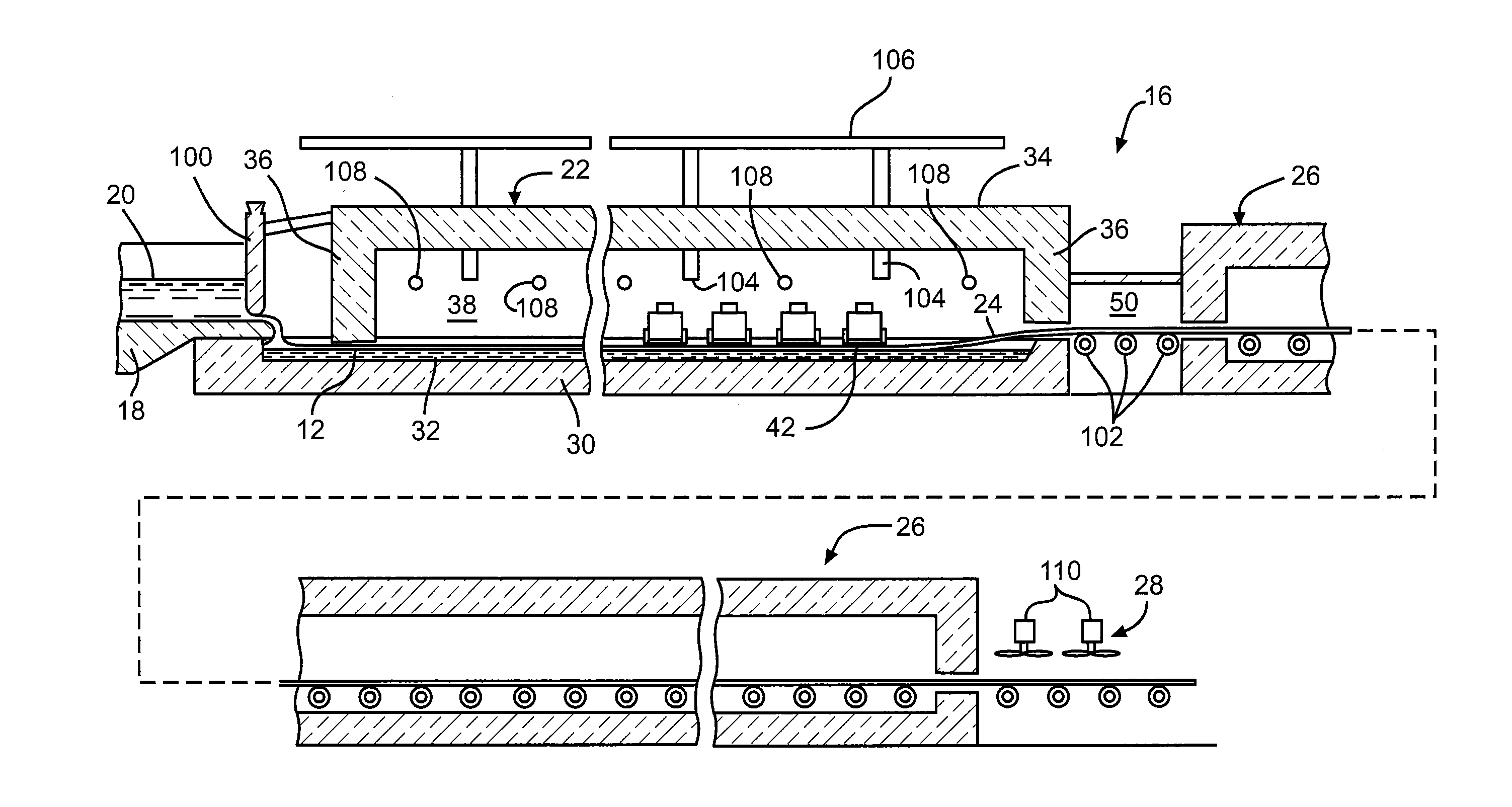
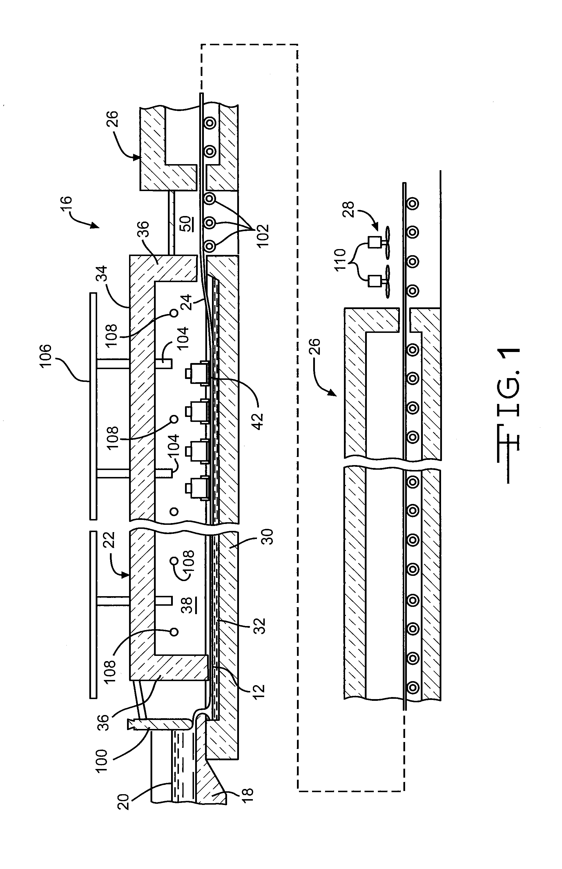
Zinc Oxide (ZnO) Deposition with an Additive Compound Using a 5 Slot Coating Apparatus
[0111]All gaseous precursor compound supply lines were maintained at above the dew point.
[0112]Slot 1 and Slot 5—Using the experimental conditions described above in connection with Comparative Example 1, a stream comprising a gaseous mixture of N2 and H2O (in the form of steam) was introduced into and through Slot 1 and Slot 5. 10 mL / min of water was injected into the evaporator and the amount of N2 added to the evaporator was such that the total flow rate of N2 and steam was equal to 20 slm, with 10 slm going to each stream in Slot 1 and Slot 5.
[0113]Slot 2 and Slot 4—A stream of 10 slm of N2 gas was introduced into each of Slots 2 and 4.
[0114]Slot 3—The composition of the gaseous stream introduced into Slot 3 was modified from that of Comparative Example 1. In this example, the stream in Slot 3 comprised gaseous DMZ and an acetonate additive compound, namely acetyl acetonate. Two bubblers were u...
example 3
Gallium Doped Zinc Oxide (ZnO:Ga) Deposition with an Additive Compound Using a 5 Slot Coating Apparatus
[0116]All gaseous precursor compound supply lines were maintained at above the dew point.
[0117]Using the experimental conditions described above in connection with Example 2, a stream comprising a gaseous mixture of N2 and H2O (in the form of steam) was introduced into Slot 1 and Slot 5. To generate the stream, 24 mL / min of water was injected into the evaporator and 0.5 slm of N2 was added. The total flow rate of the mixture was 20 slm with 10 slm of the mixture flowing through each of Slots 1 and 5.
[0118]Slot 2 and Slot 4—A stream of 10 slm of N2 gas was introduced into each of Slots 2 and 4.
[0119]The gaseous stream which was introduced into Slot 3 comprised a mixture of DMZ, acetyl acetonate and a dopant compound, namely TMG. Three bubblers were used to generate this gaseous stream mixture. The DMZ bubbler and the acetyl acetonate bubbler were operated as described in Example 2. ...
example 4
Zinc Oxide (ZnO) Deposition with an Additive Compound Using a 5 Slot Coating Apparatus
[0121]All gaseous precursor compound supply lines were maintained at above the dew point.
[0122]A stream comprising a gaseous mixture of N2 and H2O (in the form of steam) was introduced into Slot 1 and Slot 5. To generate the stream, 19.5 cc / min of water was evaporated. N2 was added so that the total flow rate of the mixture was 20 slm with 10 slm of the mixture flowing through each of Slots 1 and 5.
[0123]Slot 2 and Slot 4—A stream of 10 slm of N2 gas was introduced into each of Slots 2 and 4.
[0124]The gaseous stream which was introduced into Slot 3 comprised a mixture of DMZ and trifluoroacetylacetonate. The DMZ was evaporated so that 0.077 mol / min of gaseous DMZ was provided. The trifluoroacetylacetonate was evaporated so that 0.00092 mol / min of gaseous trifluoroacetylacetonate was provided. N2 carrier gas was added to create a total gas flow through Slot 3 of 10 slm.
[0125]Under these conditions, ...
PUM
| Property | Measurement | Unit |
|---|---|---|
| temperature | aaaaa | aaaaa |
| temperature | aaaaa | aaaaa |
| deposition rate | aaaaa | aaaaa |
Abstract
Description
Claims
Application Information