
Data acquired system and ct apparatus using the same

a data acquisition system and data acquisition technology, applied in tomography, applications, instruments, etc., can solve the problems of difficult to have uniform temperature distribution on different circuit boards, lower temperature on each circuit board, etc., and achieve the effect of less material, no effect on heat dissipation performance, and sufficient stiffness

Active Publication Date: 2012-09-27
GENERAL ELECTRIC CO
View PDF3 Cites 3 Cited by
  • Summary
  • Abstract
  • Description
  • Claims
  • Application Information

AI Technical Summary

Benefits of technology

[0008]To solve the problem of heat dissipation of the data acquired system (DAS) in the prior art, the embodiments described herein provide a new DAS and a computerized tomography (CT) apparatus using the same. The DAS described herein has an efficient heat-dissipation capability, which on the one hand lowers the temperature of electrical components and extends the service life of the electrical components, on the other hand achieves higher temperature uniformity on circuit boards and has narrow temperature distribution on different electrical boards, thereby contributing to high CT image quality. Moreover, with less material and enough stiffness, the DAS described herein is adapted to be mounted on a rotating gantry of the CT apparatus.
[0020]The embodiments described herein have at least the following advantages.
[0022]The guidance of the airflow guide and the tapering of the airflow channel direct the airflow from the fan completely to the electrical components and accelerate the airflow to be finally discharged from the air vent, thereby avoiding bypass and turbulence of the airflow and improving the heat dissipation efficiency. Consequently, different circuit boards have higher temperature uniformity and minor temperature difference, which contributes to high CT image quality.
[0023]The embodiments described herein effectively blow away heat dissipation from the electrical components, such that the electrical components in the DAS have lower working temperature, which will extend the service life of the electrical components.
[0024]With a filter assembly and an electromagnetic interference guard, the effective airflow of the DAS is compatible with electromagnetic (EMC), and has the dust-preventing performance.

Problems solved by technology

In the prior art, it is rather difficult to have uniform temperature distribution on different circuit boards and lower temperature on each circuit board.

Method used


Image

  • Data acquired system and ct apparatus using the same
  • Data acquired system and ct apparatus using the same
  • Data acquired system and ct apparatus using the same

Examples


Embodiment Construction

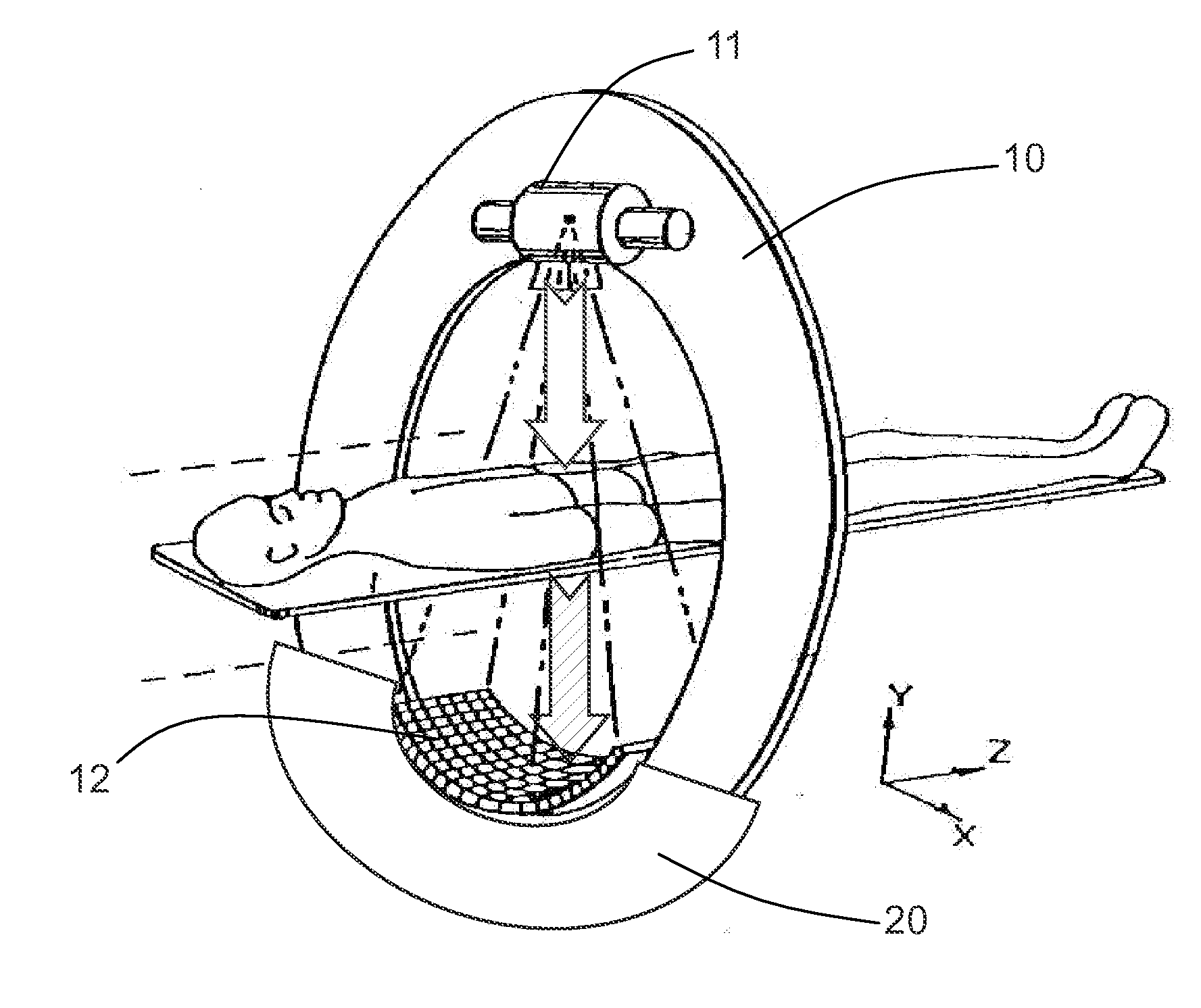
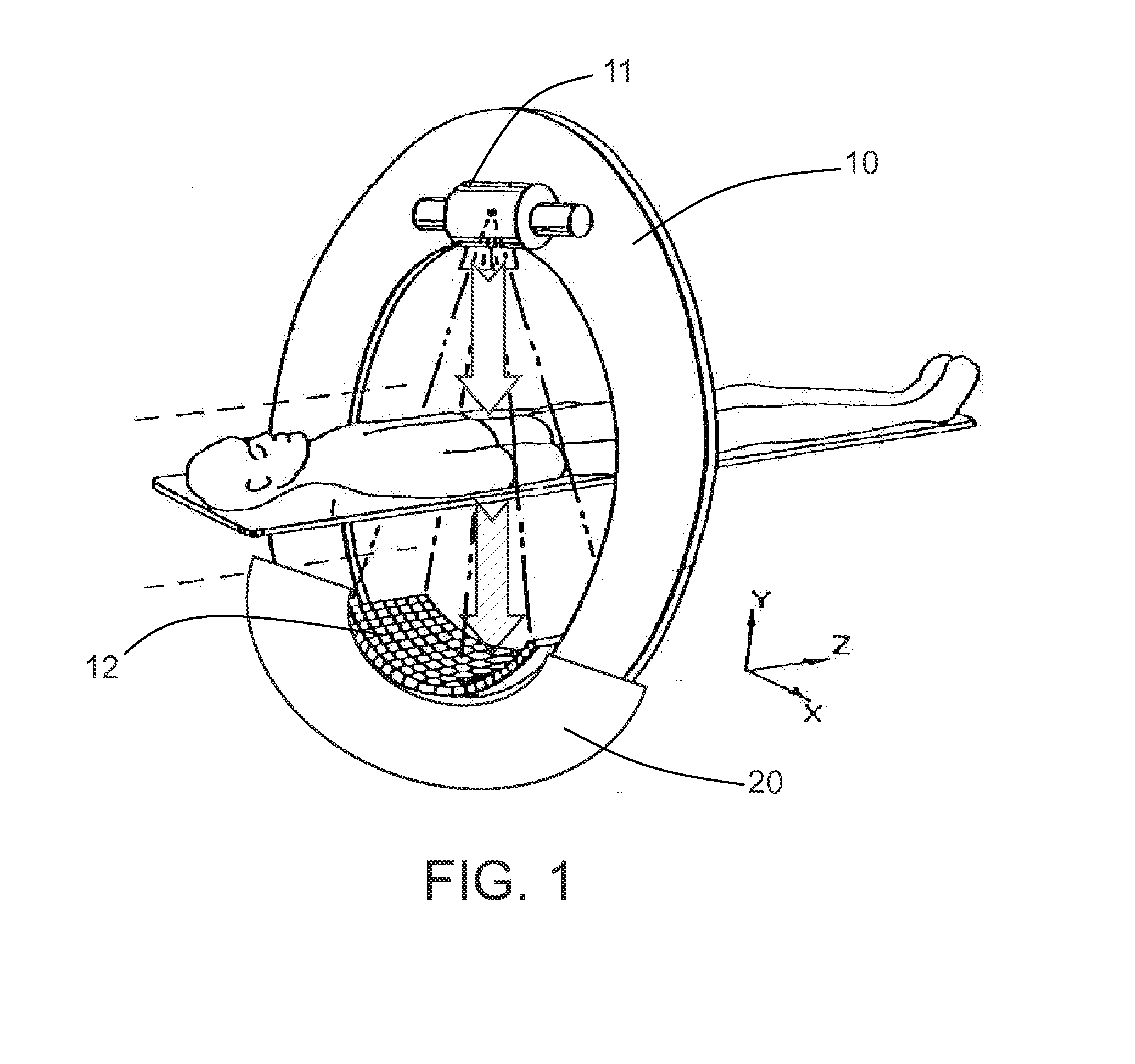
[0040]As shown in FIG. 1, the exemplary CT apparatus includes a rotatable annular gantry 10 having a hole through it, the hole being designed to receive a subject like a patient moving horizontally therethrough. The gantry 10 is provided with an X-ray source 11 configured to emit X-rays to the subject like a patient. A detector 12 is installed on the other side of the subject and configured to detect the X-rays passing through the subject. A data acquired system (DAS) 20 is disposed adjacent to the detector 12 on the same side as the gantry. The X-ray source 11 is installed on an annular section of the gantry 10 of the CT apparatus, opposing the detector 12 and the DAS 20. In the scanning process, the gantry rotates as necessary. Hence, it is desired that the DAS use less material and have enough stiffness.

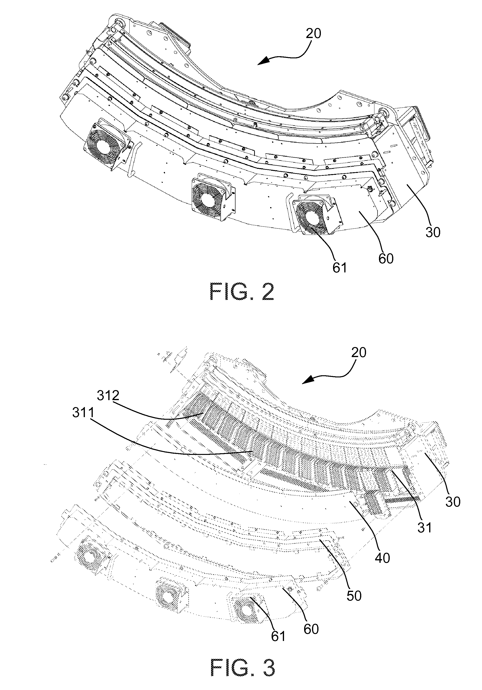
[0041]FIGS. 2 and 3 show the overall structure of a DAS 20 in an exemplary embodiment. FIG. 4 shows the main structure of the DAS, and FIG. 5 shows the construction principle of t...


PUM

PropertyMeasurementUnit
distanceaaaaaaaaaa
electromagneticaaaaaaaaaa
CTaaaaaaaaaa

Abstract

A data acquired system is provided. The data acquired system includes a main structure with a cavity formed therein, the cavity having a bottom for mounting a circuit board with electrical components thereto, a fan assembly disposed on the main structure, and an airflow guide disposed within the cavity and configured to guide airflow from the fan assembly for heat dissipation of the electrical components, the airflow guide positioned at a distance above the electrical components to form a gap between the airflow guide and the electrical components, wherein a sidewall of the cavity is provided with an air vent corresponding to the gap such that the airflow passes through the gap and is discharged from the air vent.

Description

CROSS REFERENCE TO RELATED APPLICATIONS[0001]This application claims the benefit of Chinese Patent Application No. 201110080253.0 filed Mar. 23, 2011, which is hereby incorporated by reference in its entirety.BACKGROUND OF THE INVENTION[0002]The present invention relates to computerized tomography (CT), and in particular to a data acquired system (DAS) and a CT apparatus using the same.[0003]A CT apparatus has been used for real time observation of the internal condition of an object. A typical CT apparatus includes an X-ray source configured to emit X-rays to a patient or luggage. A detector is installed on the other side of the object and configured to detect the X-rays passing through the object.[0004]For instance, the CT apparatus measures a human body based on different absorption and penetration rates of different tissues for the X-rays, and then inputs the measured data into a computer which, after processing the data, can take a sectional or stereo image for the examined par...

Claims


Application Information

Patent Timeline
Patent Type & Authority Applications(United States)
IPC IPC(8): H05G1/02H05K13/00A61B6/03
CPCA61B6/035Y10T29/49002A61B6/4488A61B6/4266
Inventor GUO, JUNZHANG, XIAOYANLIU, HAILIANGLIU, ZHUOJOSHI, ASHUTOSH
Owner GENERAL ELECTRIC CO
Learn More