
Composite components formed by coating a mold with ceramic material

a technology of ceramic material and composite components, applied in the field of composite components, can solve the problems of non-uniform distribution of ceramic materials throughout all or parts of a composite component, and achieve the effects of improving wear resistance and/or impact resistance, reducing manufacturing costs, and improving impact resistan

Inactive Publication Date: 2012-09-27
SPOKANE INDS
View PDF9 Cites 8 Cited by
  • Summary
  • Abstract
  • Description
  • Claims
  • Application Information

AI Technical Summary

Benefits of technology

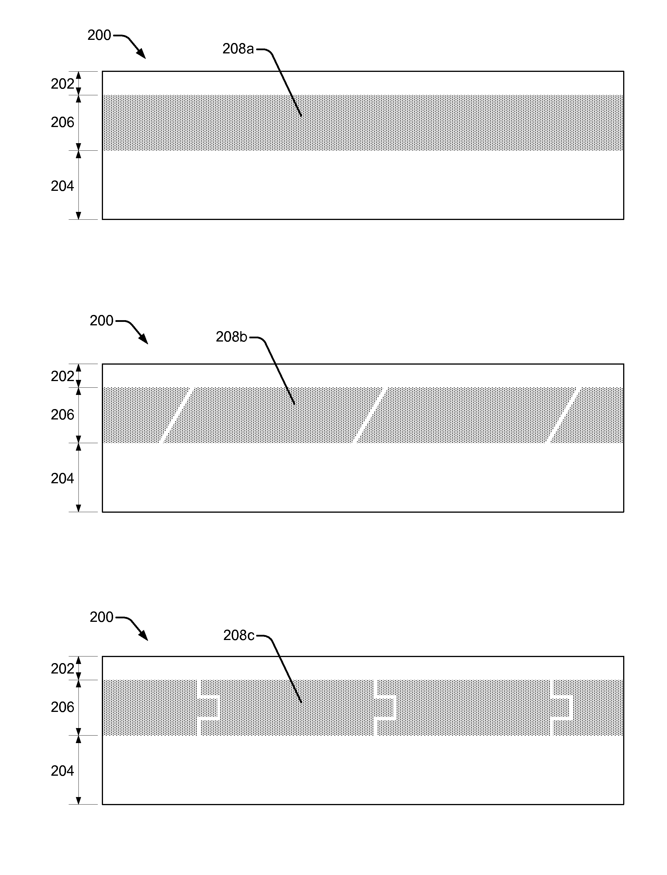
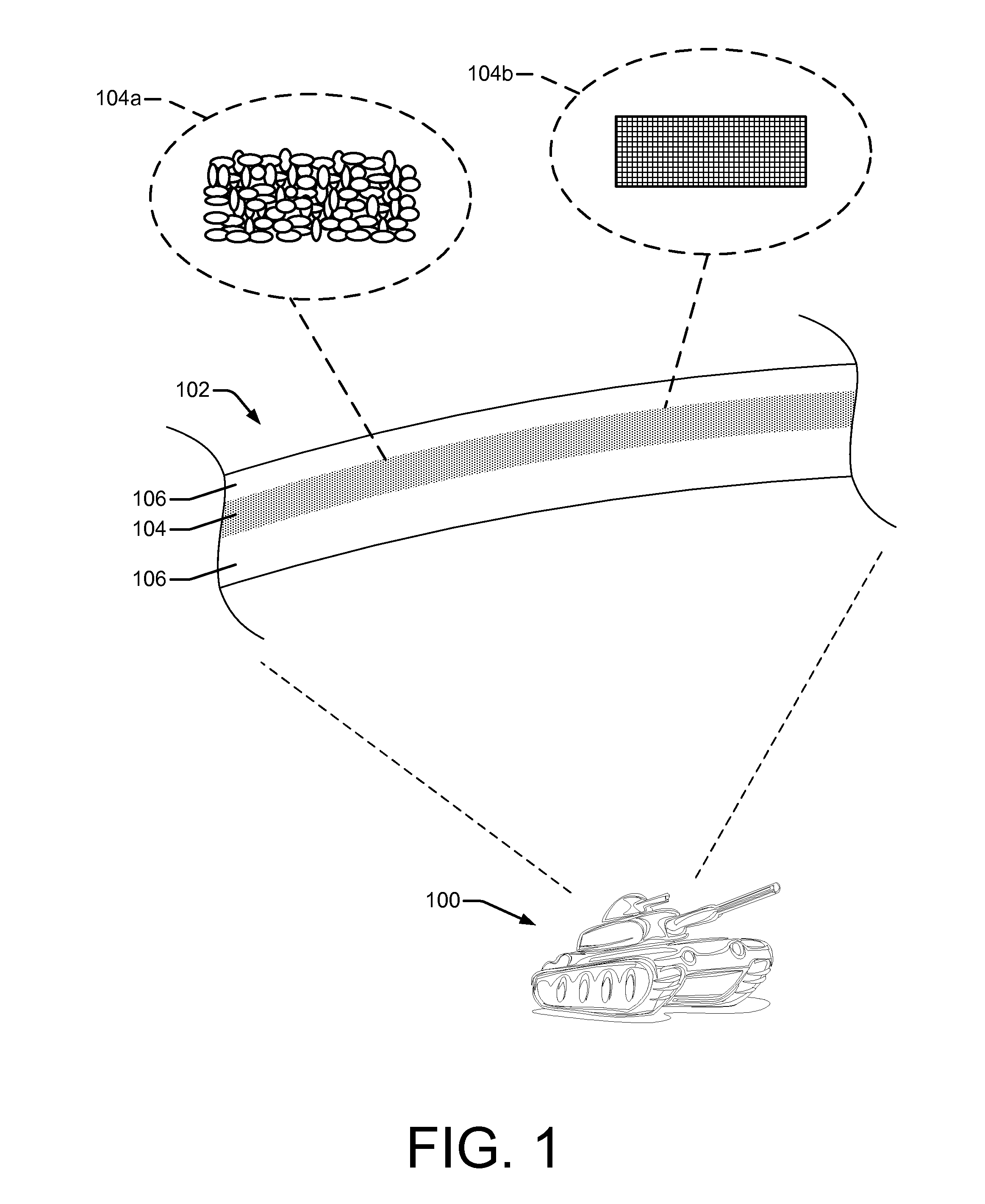
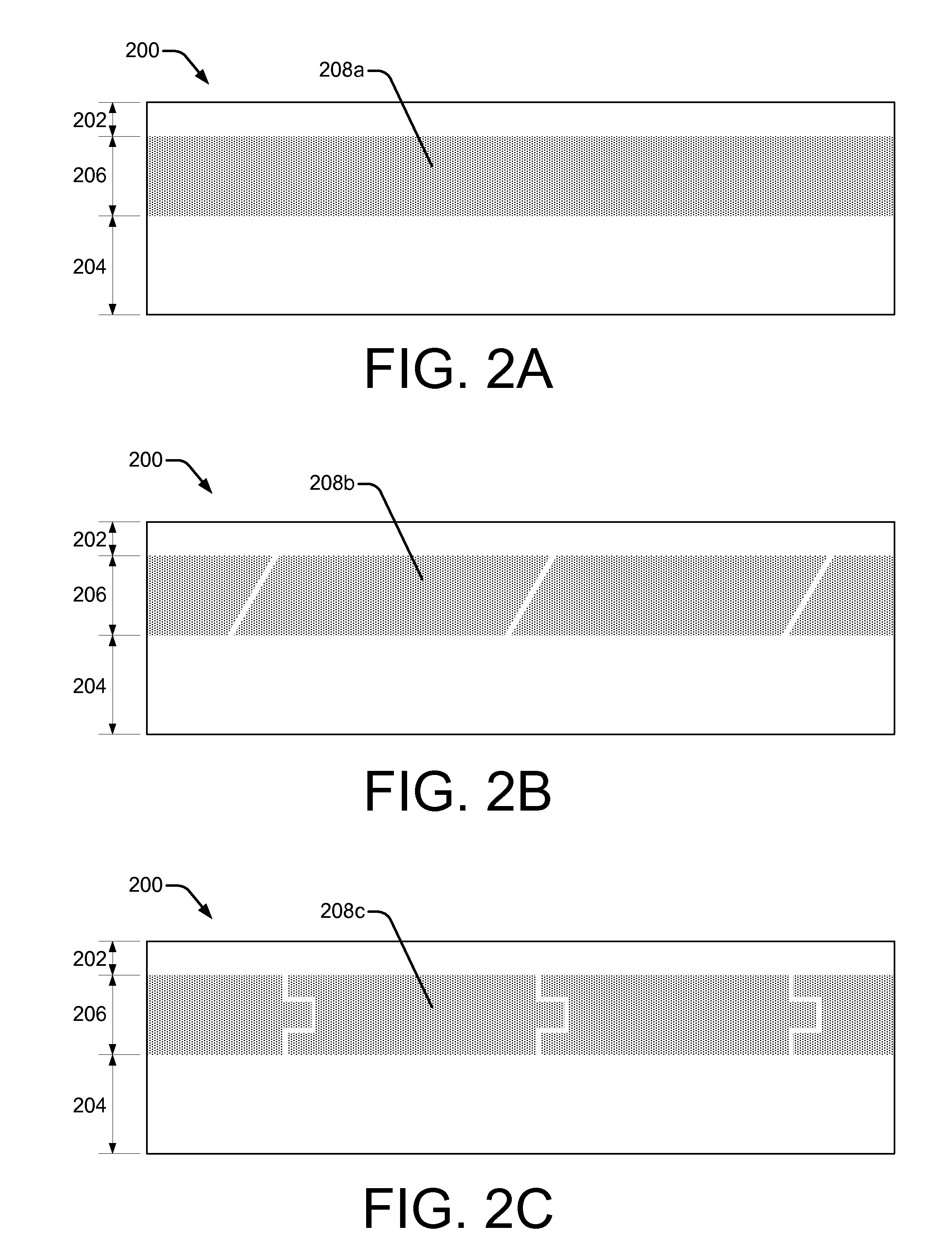
[0006]This disclosure relates to composite components that are subject to wear (so called “wear parts”) and / or impacts and techniques for forming such components. The composite components generally comprise a base metal having a ceramic material embedded therein. The composite components exhibit improved resistance to wear and / or impact and, therefore, have a longer usable life or higher impact resistance than components formed of the base metal or ceramic material alone. Composite components may be used to improve a usable life of virtually any wear part and / or to improve protection against ballistic or other impacts. While in some examples, ceramic material may be distributed uniformly throughout a component, in other examples, ceramic material may be distributed non-uniformly throughout all or part of a composite component.

Problems solved by technology

While in some examples, ceramic material may be distributed uniformly throughout a component, in other examples, ceramic material may be distributed non-uniformly throughout all or part of a composite component.

Method used


Image

  • Composite components formed by coating a mold with ceramic material
  • Composite components formed by coating a mold with ceramic material
  • Composite components formed by coating a mold with ceramic material

Examples


Embodiment Construction

Overview

[0027]As noted above, manufacturing of composite components is often difficult due to the varying material properties of the materials from which the composite component is made. This application describes composite components comprising ceramics and metal or metal alloy(s) that, together, exhibit improved resistance to wear, friction, and / or impact compared with components formed of ceramic or metal alone. This application also describes various techniques for manufacturing such composite components. By way of example and not limitation, the composite components described herein may be used in the fields of excavation, manufacturing, metallurgy, milling, material handling, transportation, construction, military applications, and the like.

[0028]In general, composite components as described in this application include a base metal and one or more ceramic materials. This application describes techniques for casting such composite components in sand and / or investment casting mo...


PUM

PropertyMeasurementUnit
thicknessaaaaaaaaaa
sizesaaaaaaaaaa
sizesaaaaaaaaaa

Abstract

Methods and processes are described that form ceramic wear surfaces on the outer surface of a cast part. A mold having a mold cavity is provided. The mold cavity may be washed using a refractory wash to provide for a smoother finish to the surface of the cast part and to maintain mold integrity. An adhesive is applied to predetermined locations in which increased wear during the use of the cast parts is anticipated to occur. Ceramic material may be applied to the predetermined locations by various means. A mask may be used to remove excess material from areas other than the predetermined locations. A molten metal is poured into the mold cavity and allowed to cool to form a cast part with a ceramic wear surface.

Description

BACKGROUND[0001]Wear or impact resistant components are desirable in a variety of industrial, commercial, and military applications. For example, mining, construction, heavy equipment, automotive, military, and other applications rely on components that are resistant to wear and impact.[0002]Recently, composite components formed of two materials having different material properties have been used. For example, a composite component may be made by combining a first material having a high hardness with a second material having a high toughness, to produce a composite component having characteristics of both materials (i.e., high hardness and toughness).[0003]However, manufacturing composite components is often challenging due to the different properties of materials used to form the composite component. For example, different materials often have different coefficients of thermal expansion, different densities, different melting points, etc. A manufacturing process that works well for...

Claims


Application Information

Patent Timeline
Patent Type & Authority Applications(United States)
IPC IPC(8): B32B15/04B32B5/00B32B18/00B22D19/14B22D19/00
CPCB22D19/14C22C1/05Y10T428/266C22C29/00C22C32/00C22C1/1036B32B9/005B32B9/041B32B15/14B32B15/18B32B2307/536B32B2307/554B32B2307/558B32B2419/00B32B2571/02B32B2605/00B22C9/00B22D19/02
Inventor TENOLD, TYRUS NEILTENOLD, GREGORY GEORGETENOLD, ROBERT GORDONKACZMAREK, EDWARD ROBERTGROZDANICH, ROD ALAN
Owner SPOKANE INDS
Learn More