Ultrasound diagnostic apparatus and method of producing ultrasound image

a diagnostic apparatus and ultrasound technology, applied in the field of ultrasonic diagnostic apparatus and a method of producing ultrasound images, can solve the problems of difficult to measure accurate sound speed, low accuracy, and large time consumption, and achieve satisfactory precision, accurate measurement of local sound speed value, and short time

Inactive Publication Date: 2012-09-27
FUJIFILM CORP
View PDF3 Cites 5 Cited by
  • Summary
  • Abstract
  • Description
  • Claims
  • Application Information

AI Technical Summary

Benefits of technology

[0008]The invention has been finalized in order to solve the problems inherent in the related art, and an object of the invention is to provide an ultrasound diagnostic apparatus and a method of producing an ultrasound image capable of an average local sound speed value in a region of interest in a short time with satisfactory precision.
[0009]An object of the invention is to provide an ultrasound diagnostic apparatus and a method of producing an ultrasound image capable of accurately measuring a local sound speed value of a low luminance region specified on a B-mode image.

Problems solved by technology

However, when a region of interest is set, and a plurality of local sound speed values in a predetermined region are obtained, a lot of time may be spent depending on the positions of the set lattice points, or the like.
With regard to the low luminance region, although there are many cases where it is effective for diagnosis to measure a local sound speed value as well as a B-mode image, since the intensity of the ultrasonic echo is low in the low luminance region, the reception signal may be likely to be influenced by noise, making it difficult to measure accurate sound speed.

Method used


Image

  • Ultrasound diagnostic apparatus and method of producing ultrasound image
  • Ultrasound diagnostic apparatus and method of producing ultrasound image
  • Ultrasound diagnostic apparatus and method of producing ultrasound image

Examples


embodiment 1

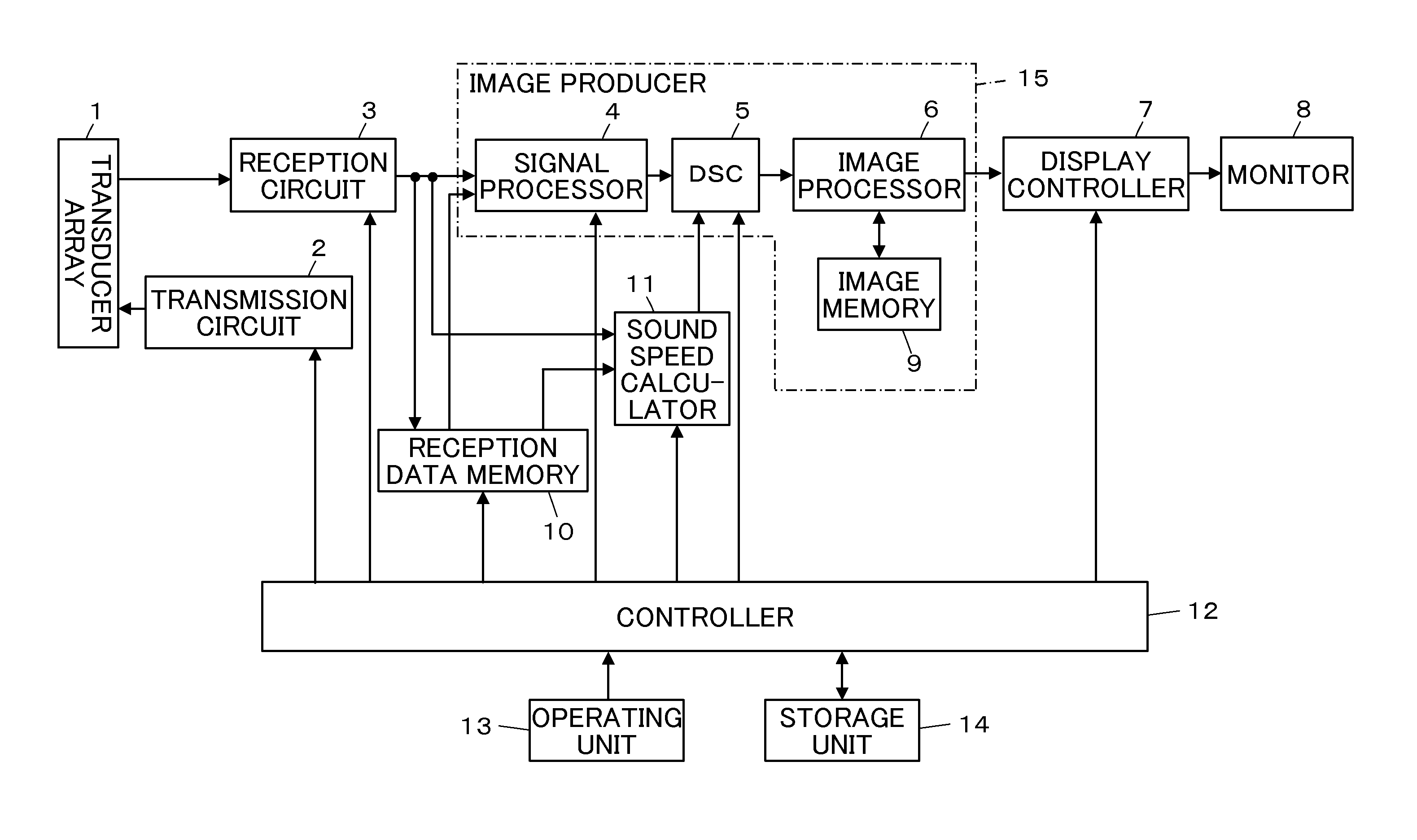
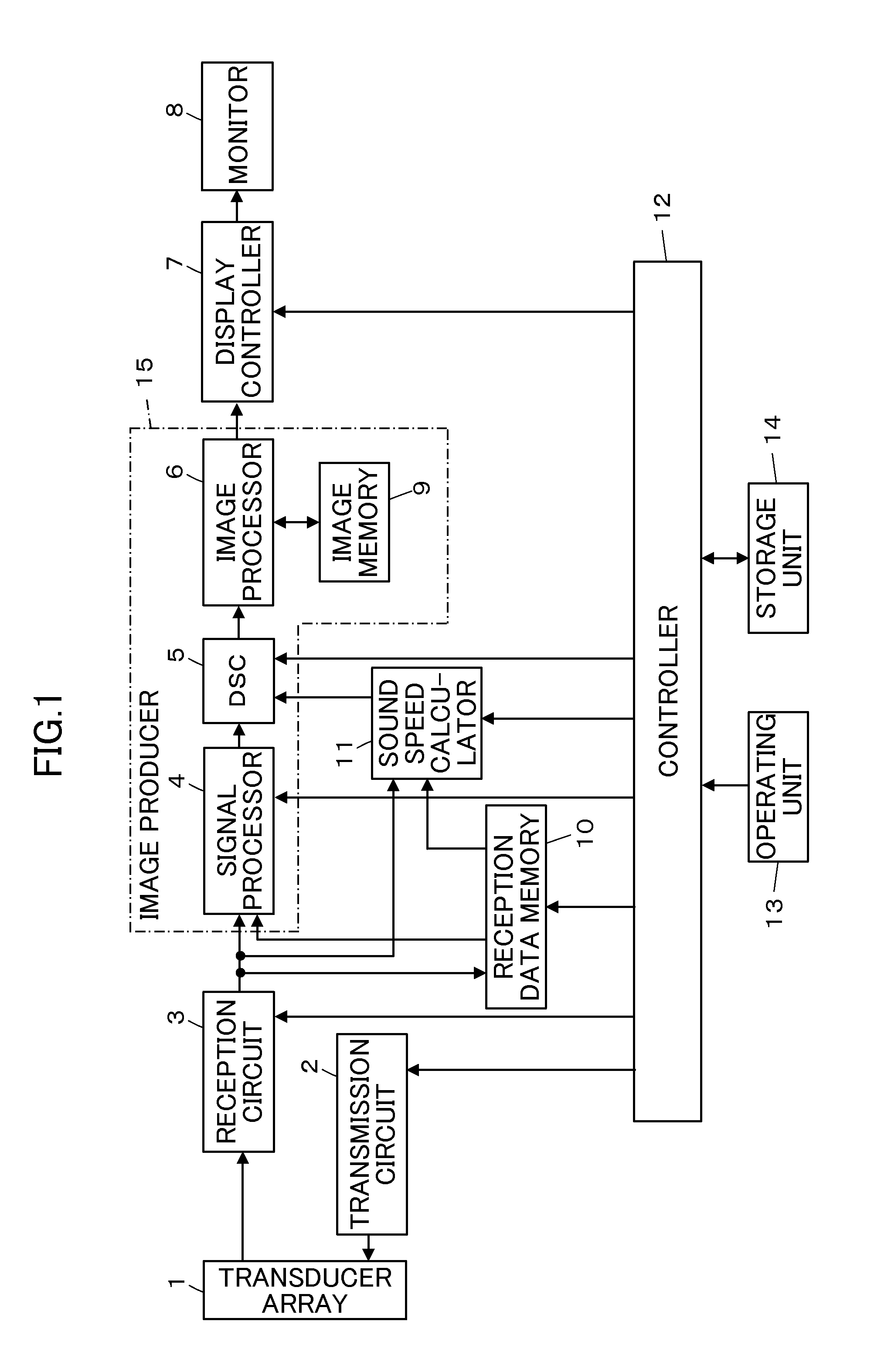
[0060]FIG. 1 shows the configuration of an ultrasound diagnostic apparatus according to Embodiment 1 of the invention. The ultrasound diagnostic apparatus includes a transducer array 1, and a transmission circuit 2 and a reception circuit 3 are connected to the transducer array 1. A signal processor 4, a DSC (Digital Scan Converter) 5, an image processor 6, a display controller 7, and a monitor 8 are sequentially connected to the reception circuit 3. An image memory 9 is connected to the image processor 6. A reception data memory 10 and a sound speed calculator 11 are connected to the reception circuit 3.

[0061]A controller 12 is connected to the signal processor 4, the DSC 5, the display controller 7, the reception data memory 10, and the sound speed calculator 11. An operating unit 13 and a storage unit 14 are connected to the controller 12.

[0062]The transducer array 1 has a plurality of ultrasound transducers arranged in a one-dimensional or two-dimensional manner. These ultrasoun...

embodiment 2

[0102]In Embodiment 1, a configuration may be made in which the average local sound speed value in the region R of interest is measured, and the sound speed map in the region R of interest is produced.

[0103]For example, as shown in FIG. 7, if a region R of interest is set on a B-mode image by an operation from the operating unit 13, the controller 12 sets lattice point E1 and E2 at a shallow position and a deep position from the region R of interest, and sets a plurality of lattice points E3 for a sound speed map indicated by “▪” in the azimuth direction at a position D3 between the lattice points E1 and E2. It is preferable that the lattice point E3 for a sound speed map is set to fall within the region of either ultrasonic beam B transmitted and received when a transmission focus is formed at each lattice point E2 set at a shallow position.

[0104]Subsequently, the controller 12 performs control such that the transmission circuit 2 and the reception circuit 3 form a transmission foc...

embodiment 3

[0107]In Embodiments 1 and 2, the sequence may be set such that, as the lattice points are at a short distance, the ultrasonic beam B which is transmitted and received when a transmission focus is formed at each lattice point set by the controller 12 is transmitted and received at a short time interval.

[0108]For example, with regard to lattice points shown in FIG. 8, a transmission focus of an ultrasonic beam can be formed in order of lattice points Ea, Ec, Ef, Ei, . . . , Eb, Ee, . . . , that is, a transmission focus of an ultrasonic beam can be sequentially formed at the lattice points at the same depth in the azimuth direction, and this can be repeated in the depth direction. A transmission focus of an ultrasonic beam may be formed in order of the lattice points Ea, Eb, Ec, Ed, Ee, . . . , that is, a transmission focus of an ultrasonic beam may be formed at the lattice points set on the same sound ray, and this may be repeated for each sound ray.

[0109]In this way, transmission an...


PUM


Abstract

An ultrasound diagnostic apparatus includes a region of interest setter which sets a region of interest on a B-mode image, a controller which performs transmission and reception of ultrasonic beams with forming transmission focuses at a plurality of points set on sound rays at a shallower position and a deeper position than the region of interest to acquire reception data for sound speed measurement, and a sound speed calculator which calculates an average local sound speed value in the region of interest on the basis of reception data for sound speed measurement.

Description

BACKGROUND OF THE INVENTION[0001]The present invention relates to an ultrasound diagnostic apparatus and a method of producing an ultrasound image, and in particular, to an ultrasound diagnostic apparatus which performs transmission and reception of ultrasonic waves with respect to a transducer array of an ultrasound probe to perform both B-mode image production and sound speed measurement.[0002]An ultrasound diagnostic apparatus using an ultrasound image has hitherto been put into practical use in the field of medicine. In general, this type of ultrasound diagnostic apparatus has an ultrasound probe embedded with a transducer array and an apparatus body connected to the ultrasound probe. An ultrasonic beam is transmitted from the ultrasound probe toward a subject, an ultrasonic echo from the subject is received by the ultrasound probe, and the reception signal is electrically processed by the apparatus body to produce an ultrasound image.[0003]In recent years, in order to diagnose ...

Claims


Application Information

Patent Timeline
Patent Type & Authority Applications(United States)
IPC IPC(8): A61B8/14
CPCG01S7/52036G01S7/52049G01S7/52085G10K11/346G01N2291/106A61B8/5207A61B8/5269A61B8/52G01N2291/02475G01N29/07A61B8/00G01N29/0672
Inventor MIYACHI, YUKIYA
Owner FUJIFILM CORP
Why Eureka
Try Eureka