Pressure sensor, sensor array, method for manufacturing sensor array, and grasping apparatus

a technology for pressure sensors and sensors, applied in the direction of manufacturing tools, force/torque/work measurement apparatus, instruments, etc., can solve the problems of apicale or diaphragm of the membrane being likely to be broken, and achieve the effect of increasing the driving speed of the grasping arms, and reducing the time until the grasping arms approach the obj

Active Publication Date: 2012-10-04
SEIKO EPSON CORP
View PDF4 Cites 38 Cited by
  • Summary
  • Abstract
  • Description
  • Claims
  • Application Information

AI Technical Summary

Benefits of technology

[0049]According to this configuration, when an object is away from the grasping arms, the driving speed of the grasping arms is increased for operation, whereby the time until the grasping arms approach the object can be shortened. When the object is close to the grasping arms, the driving speed of the grasping arms is reduced, whereby a collision between the grasping arms and the object can be avoided. After the contact of the object with the grasping arms, grasping pressure can be adjusted using a signal from the pressure sensor. That is, it is possible to provide a grasping apparatus which can grasp an object with precise grasping pressure in a short time.

Problems solved by technology

In this case, since the object directly contacts the piezoelectric film exposed to the outside, a force is locally applied to the piezoelectric body or diaphragm of the membrane, causing a problem that the piezoelectric body or diaphragm of the membrane is likely to be broken.

Method used


Image

  • Pressure sensor, sensor array, method for manufacturing sensor array, and grasping apparatus
  • Pressure sensor, sensor array, method for manufacturing sensor array, and grasping apparatus
  • Pressure sensor, sensor array, method for manufacturing sensor array, and grasping apparatus

Examples


first embodiment

Schematic Configuration of Grasping Apparatus

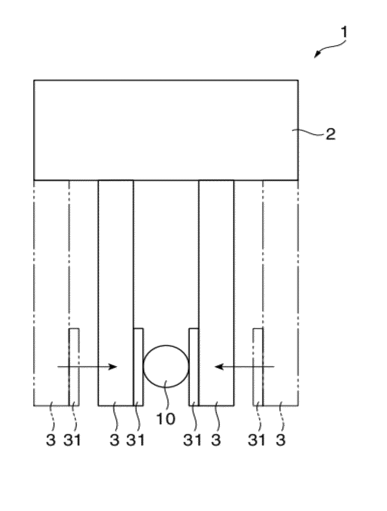
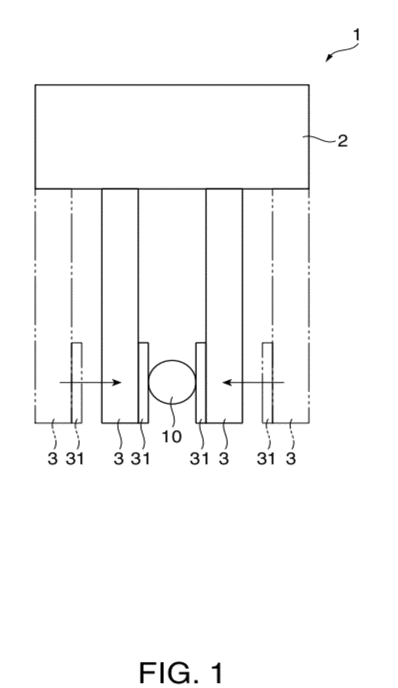
[0080]FIG. 1 is a schematic view of a grasping apparatus 1.

[0081]The grasping apparatus 1 is an apparatus which grasps, for example, an object 10. The grasping apparatus 1 recognizes the position of the object 10 to grasp the object. The grasping apparatus 1 includes a supporting member 2 and a pair of arms 3 as grasping arms which extend from the supporting member 2.

[0082]The supporting member 2 is formed in a longitudinal rod shape and includes a drive mechanism which moves the pair of arms 3 toward and / or away from each other.

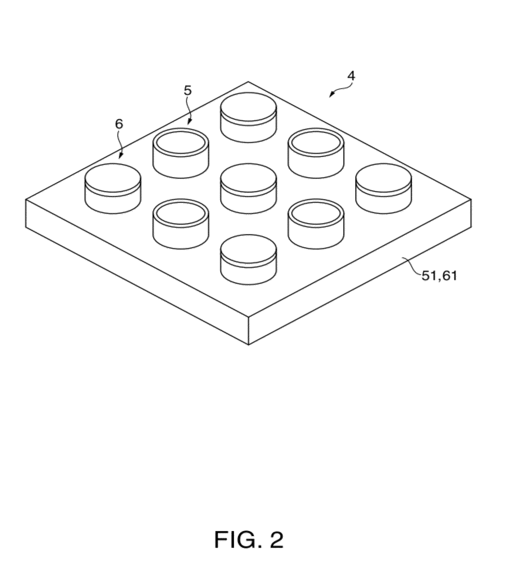
[0083]The arms 3 are portions which grasp the object 10 and operate in directions toward and / or away from each other. At a portion of the arm 3 with which the object 10 contacts, a substantially rectangular grasping surface 31, for example, is formed. A sensor array 4 (refer to FIG. 2) is attached to the grasping surface 31.

Configuration of Sensor Array

[0084]FIG. 2 is a perspective view showing a sensor array incl...

second embodiment

Configuration of Sensor Array

[0144]FIG. 9 is a perspective view showing a sensor array 180 according to the second embodiment. FIG. 10A is a plan view of the sensor array 180 shown in FIG. 9; FIG. 10B is a cross-sectional view taken along line A-A′ shown in FIG. 10A when the object 10 contacts the sensor array; and FIG. 10C is a cross-sectional view taken along the line A-A′ when a greater pressure than usual is applied in a state of grasping the object 10.

[0145]The sensor array 180 is, for example, a tactile sensor having excellent resistance to pressure and outputs, as an electric signal, pressure between the object 10 and the sensor array 180 as shown in FIGS. 10A to 10C. The sensor array 180 includes a plurality of pressure sensors 106 which are mounted on a supporting body 161. The sensor array 180 differs from the sensor array of the first embodiment in that a groove G as a gap is arranged so that when a smaller pressure than an allowable pressure of the pressure sensor 106, n...

third embodiment

Configuration of Sensor Array

[0188]FIG. 13 is a perspective view showing a sensor array 281. FIG. 14A is a plan view of the sensor array 281 shown in FIG. 13; and FIG. 14B is a cross-sectional view taken along line A-A′ of the plan view shown in FIG. 14A. The sensor array 281 includes ultrasonic sensors 205 in addition to pressure sensors 206.

[0189]The sensor array 281 is, for example, a tactile sensor which can detect distance information and pressure information. The sensor array 281 includes the plurality of ultrasonic sensors 205 each of which outputs distance information as an electric signal when the object 10 is away from the sensor array 281, and the plurality of pressure sensors 206 each of which outputs, as an electric signal, the pressure between the object 10 and the sensor array 281 when the object 10 contacts the sensor array 281. The sensor array 281 differs from the sensor array 180 in the second embodiment (for example, refer to FIGS. 10A and 10B) in including the p...


PUM

PropertyMeasurementUnit
thicknessaaaaaaaaaa
thicknessaaaaaaaaaa
thicknessaaaaaaaaaa

Abstract

A pressure sensor includes: a supporting body which has an opening; a pressure detecting portion which includes a supporting film provided on the supporting body and having a diaphragm portion closing the opening, and a piezoelectric body provided on the diaphragm portion and deflecting to output an electric signal; a frame body which has, on the pressure detecting portion, a cylindrical cavity along a film thickness direction of the supporting film, and is formed, in plan view when viewed from the film thickness direction of the supporting film, at a position where a cylindrical inner peripheral wall of the cavity overlaps with the opening, or outside of the opening; a sealing film which closes the frame body; and a silicone oil which is filled in an inner space formed of the cylindrical inner peripheral wall of the cavity, the sealing film, and the pressure detecting portion.

Description

BACKGROUND[0001]1. Technical Field[0002]The present invention relates to a pressure sensor, a sensor array, a method for manufacturing a sensor array, and a grasping apparatus.[0003]2. Related Art[0004]Diaphragm-type ultrasonic sensor devices have been known in the related art (for example, refer to JP-A-2006-319945).[0005]This type of ultrasonic sensor device includes a semiconductor substrate having an opening, two layers of electrodes on an insulating film formed on the surface of the semiconductor substrate to close the opening, and a PZT ceramic thin film layer (piezoelectric film) interposed between the two layers of electrodes. Then, a membrane which has a diaphragm with a multilayer film structure stacked in a planar manner with respect to the opening and a piezoelectric body configured of the piezoelectric film and the two layers of electrodes is formed. In the ultrasonic sensor device, when a predetermined voltage is applied from the upper and lower electrodes to the PZT c...

Claims


Application Information

Patent Timeline
Patent Type & Authority Applications(United States)
IPC IPC(8): G01L9/08H01L41/22
CPCB25J13/082H01L41/1132H01L41/332G01L1/02Y10T29/42H01L41/22H01L27/20G01L5/226H10N39/00H10N30/302H10N30/082G01L9/08G01L9/0022G01L11/06H10N30/01
Inventor SUZUKI, HIRONORI
Owner SEIKO EPSON CORP
Why Eureka
Try Eureka