Resonance engine

a technology of resonance engine and engine body, which is applied in the direction of machines/engines, mechanical vibration separation, ornithopters, etc., can solve the problems of increasing difficulty, affecting efficiency, and affecting efficiency, so as to achieve optimum efficiency, reduce weight, and achieve effective control

Active Publication Date: 2012-10-04
MAPLEBIRD
View PDF11 Cites 20 Cited by
  • Summary
  • Abstract
  • Description
  • Claims
  • Application Information

AI Technical Summary

Benefits of technology

[0041]Whereas the engine may include all components required in order to operate in an automated, stand-alone manner, in some embodiments, the resonant engine includes means to operate the drive signal generator remotely. This function enables the engine to be operated remotely, for example by a human or virtual operator. In contrast to embodiments where all operation is stand-alone, this also enables certain components to be left off the engine, thereby minimising its weight.
[0042]Where the engine has more than one spring-mass resonator, the various spring-mass resonators are preferably so tuned and arranged that the torque force moments generate...

Problems solved by technology

Creating efficient and controllable, insect sized NAVs that are capable of controlled, hovered flight and terrestrial locomotion is proving a considerable challenge.
A NAV engine's thrust-to-weight ratio needs to be high enough as is required to lift the power source and control electronics, this being increasingly difficult to achieve with decreasing scale due to the non-linear scalability of component power densities.
Higher wing beat frequencies offer more efficient lift and improved flight stability in windy conditions but the increased frictional energy losses in the motor and transmission systems have a detrimental consequence for efficiency, and engine longevity as related to structural fatigue engine failure.
The difficulties in creating sufficient thrust-to-weight engine performance, at progressively smaller scales of typically less than 3 cm wingspan, is driving a considerable effort in the industry, to reduce motor, airframe and transmission weight whilst increasing strength and power density.
If more appendages, such as legs with terrestrial locomotion, are added...

Method used


Image

  • Resonance engine
  • Resonance engine
  • Resonance engine

Examples


first embodiment

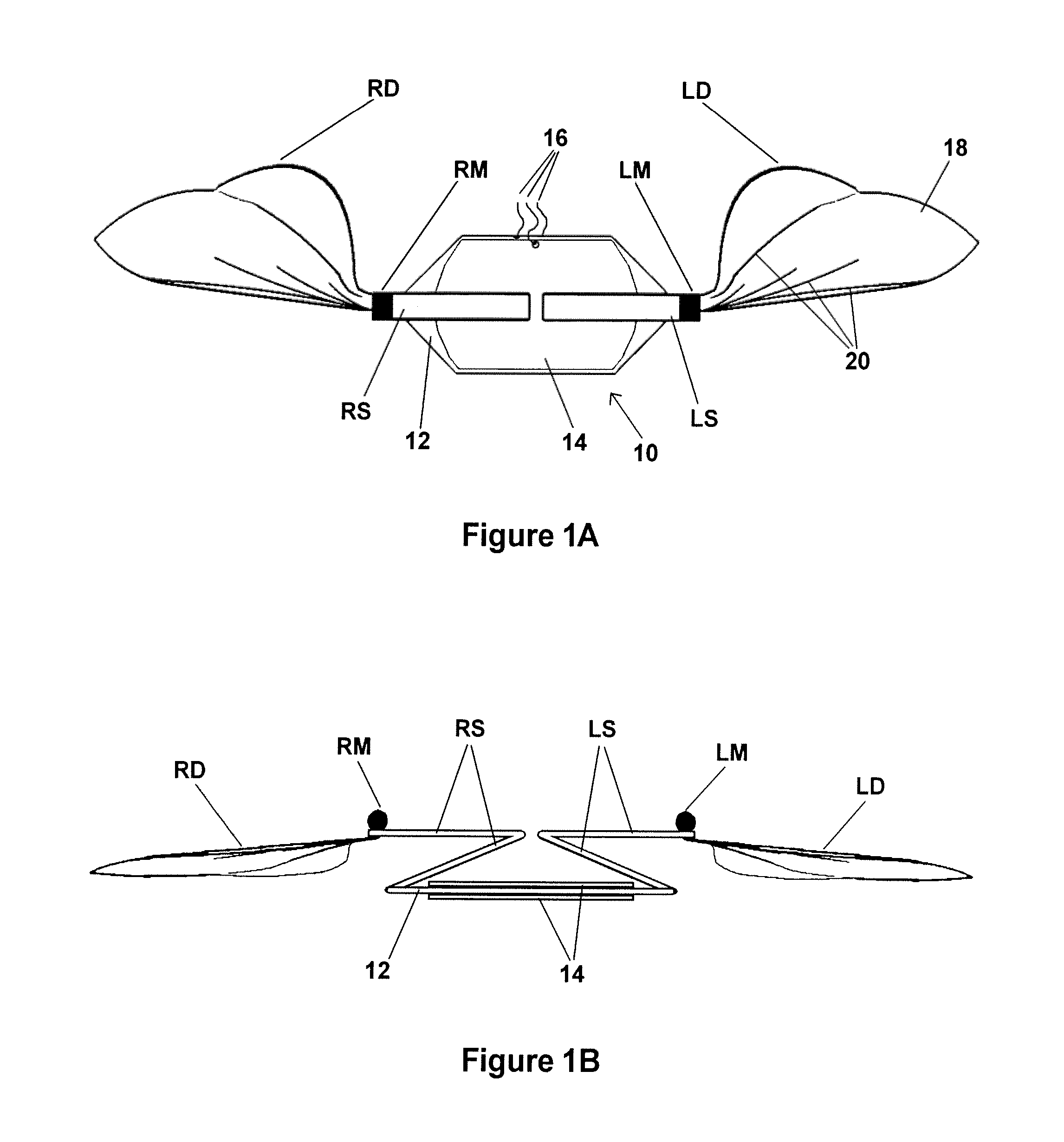
[0044]FIGS. 1A and 1B are respective plan and front elevation views of a NAV having a resonant engine in accordance with the present invention;

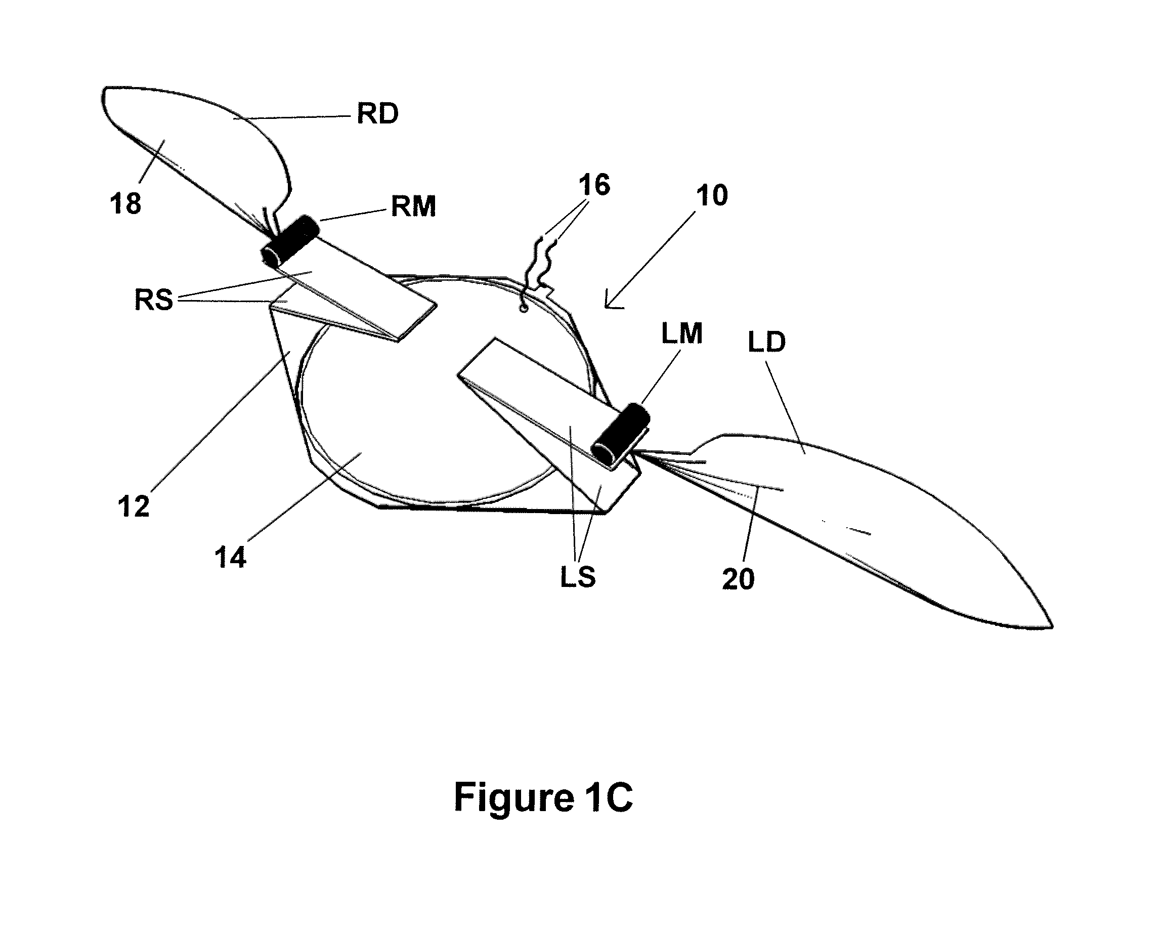
[0045]FIG. 1C is an isometric view of the NAV of FIGS. 1A and 1B;

[0046]FIG. 2 shows four wing stroke positions of a schematic NAV with its attitude orientated for static hover and revealing the vertical, horizontal and rotational components of the wing and resonator kinematics;

[0047]FIGS. 3A and 3B show front elevations of three wing positions in the up stroke and then down stoke;

[0048]FIGS. 4A-4D each show schematic NAVs in the top and bottom of the wing stroke positions with wing stroke amplitudes for, respectively: high lift, low lift, roll left, and roll right;

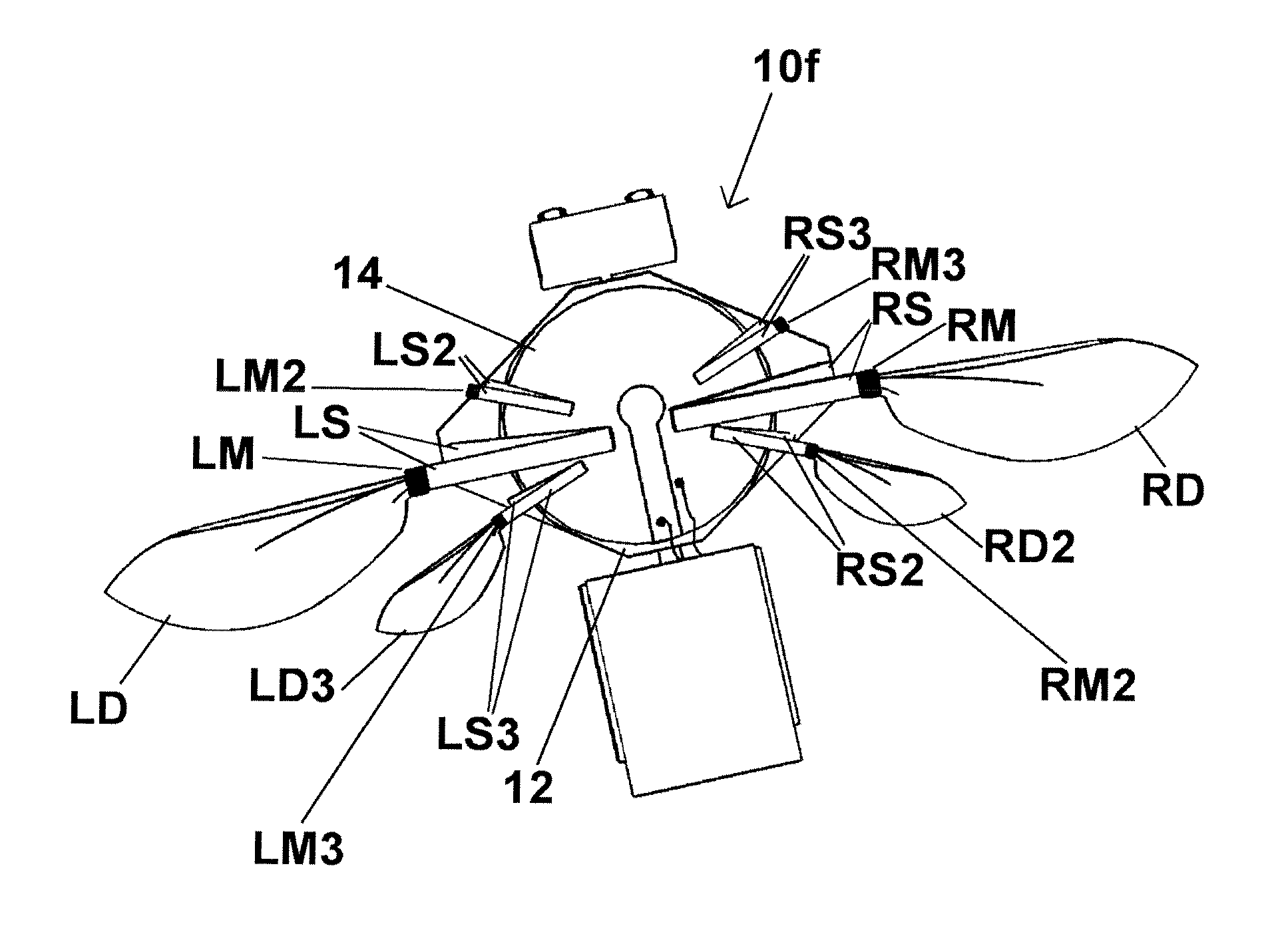
[0049]FIGS. 5A and 5B show respective top and underside views of a remote controlled micro mechanical insect incorporating a resonant engine in accordance with another embodiment of the invention, contrasting with the first embodiment by the addition of six leg resonators, a power s...


PUM


Abstract

A resonance engine is disclosed comprising: a driver plate (12), to which is coupled at least one oscillatory transducer (14); a drive signal generator connected to the oscillatory transducer for excitation thereof; a first spring-mass resonator, having a first natural resonant frequency, with a proximal end attached to the driver plate (12) and a free distal end; and a reaction means attached to the driver plate substantially opposite to the first spring-mass resonator. When the oscillatory transducer (14) is excited by a drive signal from the generator having a component at or close to said natural resonant frequency, the first spring-mass resonator oscillates at resonance, substantially in anti-phase to the driver plate (12).
Small vibrational strains in the oscillatory transducer (14) are converted to large strains of controllable kinematic movements.
The resonance engine has particular application for nano air vehicles (10-10f), wherein at least one spring-mass resonator is fitted with a wing (RD, LD) capable of producing thrust by flapping in an insect like kinematic manner suitable for flight. Where additional spring-mass resonators are added to the engine, each may be fitted with a wing. Each different spring-mass resonator may be tuned to have a different natural resonant frequency (when measured in isolation), whereby flight may be controlled by adjusting the drive signal; at particular drive frequencies, certain of the resonators may resonate in preference to others, thereby increasing lift from the associated wings, and controlling flight. The wings may face in opposite directions in order to produce rotational flight.
Further closely tuned spring-mass resonators that are tuned on a substantially different frequency band to the wing resonators can be added as legs for independently controllable terrestrial or aerial locomotion.

Description

FIELD OF THE INVENTION[0001]This invention relates to a resonance engine, which is particularly suitable for ornithopter flying devices known as nano air vehicles (NAV), and especially to miniature multimodal electromechanical insects capable of flying and terrestrial locomotion.BACKGROUND TO THE INVENTION[0002]Creating efficient and controllable, insect sized NAVs that are capable of controlled, hovered flight and terrestrial locomotion is proving a considerable challenge. A NAV's scale as generally understood in the industry is defined as being less than 7.5 cm wingspan and 10 g in weight, however current design efforts are aimed at smaller scales less than 3 cm wingspan and 1 g in weight.[0003]A NAV engine's thrust-to-weight ratio needs to be high enough as is required to lift the power source and control electronics, this being increasingly difficult to achieve with decreasing scale due to the non-linear scalability of component power densities. To keep the thrust-to-weight rati...

Claims


Application Information

Patent Timeline
IPC IPC(8): B64C33/02F03G3/00H01L41/09
CPCB64C33/02B64C2201/025B64C39/028B64U10/40B64U10/80B64U30/12B06B1/0603B64C33/025H10N30/204
Inventor GREENYER, GUY THOMAS
Owner MAPLEBIRD
Why Eureka
Try Eureka